HSS Column Splices
By Mike Manor, PE, MLSE
Forse Consulting Technical Consultant to the Steel Tube Institute
January 2018
Hollow Structural Sections (HSS) columns are prevalent in many types of construction, especially in common cases such as low-rise retail buildings. In reality, HSS columns can be a great option for taller buildings as well with its aesthetically pleasing shape, simple framing connections and small footprint. As with their wide flange counterpart, transportation limits to a construction site will require these taller columns to be shipped in multiple pieces and assembled together in the field. That is when splices become a requirement to consider as part of the design process. This article will discuss many of the splice design and fabrication requirements for various situations.
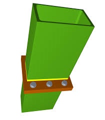
Column Splices
Due to typical transportation limitations on U.S. roadways, a good rule of thumb is to assume a maximum column length of 55 to 60 feet. Another reason for a splice may be to simplify construction in the field. Depending on the geometry and floor plan of the building, there may be times when construction sequencing requires a splice to prevent interference during installation of various portions of the building structure and components.
The function of the splice is to transfer the axial, shear and flexural forces from one column piece to the next ensuring continuity of the column and stability during erection. The splice design and detailing should consider the fabrication process and field erection as much as possible. It is critical for the splice to ensure axial forces are transmitted concentrically from the upper column to the lower column to avoid adding flexural moments due to eccentricity that have not been designed for. Part 14 of the AISC 15th Edition Steel Construction Manual (AISC, 2017) discusses detailing and splice options for dealing with these issues for the traditional wide flange columns, but unfortunately does not address HSS columns. To help supplement this information, several HSS splice options are discussed below.
Seismic Detailing
When a structure is located in geographic areas with a seismic design category of B or higher, additional seismic detailing for splices may be required per AISC 341-10 (AISC, 2010b). The first item to consider is the lateral force resisting system of the building and the corresponding response modification coefficient (R). When R is equal to 3 or less in seismic design category B or C, seismic detailing is not required. If the value of R is greater than 3 or the seismic design category is C or higher, then the seismic detailing requirements of the splice must be met. The seismic provisions must be reviewed carefully as splices require seismic detailing even when the column is not considered to be part of the seismic force resisting system. Some of the seismic detailing requirements for splices include minimum horizontal shear capacity, locations of the splices relative to the building diaphragms, and verification that the columns above and below the splice meet the seismic compactness requirements. Refer to AISC 341-10 for all seismic detailing requirements.
End Plate Splice
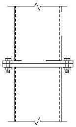
The end plate column splice is simple to design, detail and construct, thus it is likely one of the most economical splice options. The splice consists of welding an end plate with bolt holes onto the ends of both the upper and lower column sections. The erection time in the field is minimal since only bolts are required to fasten the splice together. For a pinned splice, the end plates and bolts can be chosen as nominal sizes as long as they are adequate for shear forces that may be present. Should a moment splice be required, the end plate can be sized for flexure similar to a baseplate with moment using the procedures demonstrated in AISC Design Guide #1 (AISC, 2006) along with a prying check for the bolts per AISC Design Guide #24 (AISC, 2010a). The main drawback to the end plate splice is that since the plates extend beyond the faces of the HSS column, it may not fit within the architectural aesthetic requirements or may interfere with the installation of cladding elements.
Side Plate Splice
The side plate splice makes use of direct bearing of the upper column on the lower column to transfer the axial compression. The side plates at the column walls transfer the remaining loads and serve as guides to ensure alignment, therefore, column segments on each side of the splice must have the same nominal size. The side plates are shop attached to the lower column with either welds or bolts and can be located on either the inside or outside of the column walls. The upper column is attached to the side plates in the field with either bolts or fillet welds. The field bolting option is limited because standard bolt installation requires access to both sides of the bolt which in this case is not possible. Therefore, proprietary blind structural fastener solutions must be used which allow installation with access to one side only.
For one-sided or blind structural fastener solutions for the side plate splice, including the Shuriken and Hollo-Bolt, read the HSS Insider article: HSS Blind Structural Fasteners
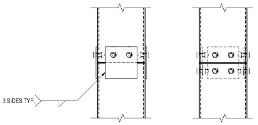
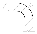
The transfer of axial compression from the upper to lower column segments appears to be straight forward, especially with the alignment plates ensuring direct bearing. However, the intricacies in the geometry of the HSS section warrant a closer look at the bearing strength. Using Equation J7-1 in the AISC 360-16 (AISC, 2016), the important variable for this case is the projected area in bearing, Apb. The bearing area becomes critical when the two column segments have different thicknesses because the corner bending radius in HSS sections varies based on the thickness. A thin HSS section has a small corner radius which means that when it is sitting on a thicker HSS section with a larger corner it is possible that the corners of the thinner section may extend beyond the thicker column. Since the corners do not align, the actual bearing area is less than the area of the full HSS section and must be checked closely.
Directly Welded Splice
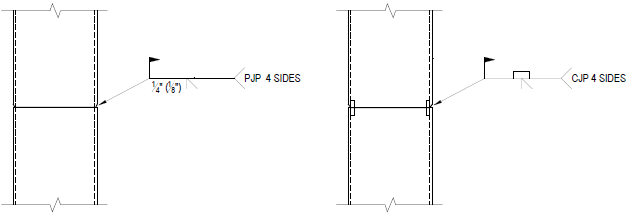
Perhaps the easiest splice to design is the direct welded splice, however, it may also be the most expensive splice option. As with the side plate, the axial compression is transmitted through direct bearing of the column ends. Using a complete joint penetration (CJP) weld will provide the strongest splice resulting in full moment capacity of the HSS section. However, there are three major drawbacks to detailing a CJP welded splice. First, it takes a highly qualified welder a significant amount of time to complete the weld. Second, a CJP weld requires special inspection which increases the cost and can impact the schedule depending on the timing of the installation and inspections. Third, backing material is required on the inside of the tube further increasing the cost due to extra fabrication time in addition to prepping the top column with bevels for the weld. In some cases, the seismic provisions require the backing material for CJP welds be removed after the weld is complete which is not possible since the inside of the column is not accessible after the weld is in place.
A partial joint penetration weld (PJP) is a more economical alternative for the directly welded splice. The bevel prep work is still required during fabrication, however, the weld takes less time in the field, the backing material is not needed and the special inspections are not required. When detailing the splice, the HSS shall have sufficient thickness to meet the geometric requirements of the PJP weld. The weld still develops a high amount of strength, thus the moment capacity of the splice can still be large if needed.
Conclusion
Splices for HSS columns are required in building construction for various reasons, such as transportation and construction limitations. Splices allow the HSS columns to be installed in multiple pieces, yet preserve structural continuity. Various splice options are available for HSS columns and the project specific requirements will dictate which splice type is the best fit for integrating the structural loads and construction costs. Remember that the easiest splice to design may not be the most economical option, especially in large buildings with many splices.
References
AISC. 2006. “Steel Design Guide Series 1: Base Plate and Anchor Rod Design Second Edition”, American Institute of Steel Construction, Chicago, IL.
AISC. 2010a. “Steel Design Guide Series 24: Hollow Structural Section Connections”, American Institute of Steel Construction, Chicago, IL.
AISC. 2010b. “Seismic Provisions for Structural Steel Buildings”, ANSI/AISC 341-10, American Institute of Steel Construction, Chicago, IL.
AISC. 2016. “Specification for Structural Steel Buildings”, ANSI/AISC 360-16, American Institute of Steel Construction, Chicago, IL.
AISC. 2017. “Steel Construction Manual, Fifteen Edition”, American Institute of Steel Construction, Chicago, IL.
Related Resources
- HSS Splices
- New Concepts for Bolted HSS Column Splices
- Meeting in the Middle: Understanding the Sales and Engineering Sides of Bolted HSS Column Splices
- All About the New Cast Steel Insert From Bull Moose Tube
- Webinar On Demand: HSS Connections: Splices, Bases, & Braces
- Webinars On Demand: HSS Splices
- Hidden Bolted HSS Splices
- Novel Bolted HSS Splice Connection
HSS Resources
Access valuable HSS tools and resources, including live webinars, producer capability tool, spreadsheet design aids, manuals, articles and more.