Hidden Bolted HSS Splices
By Jeffrey A. Packer
Bahen/Tanenbaum Professor of Civil Engineering, University of Toronto, Ontario, Canada
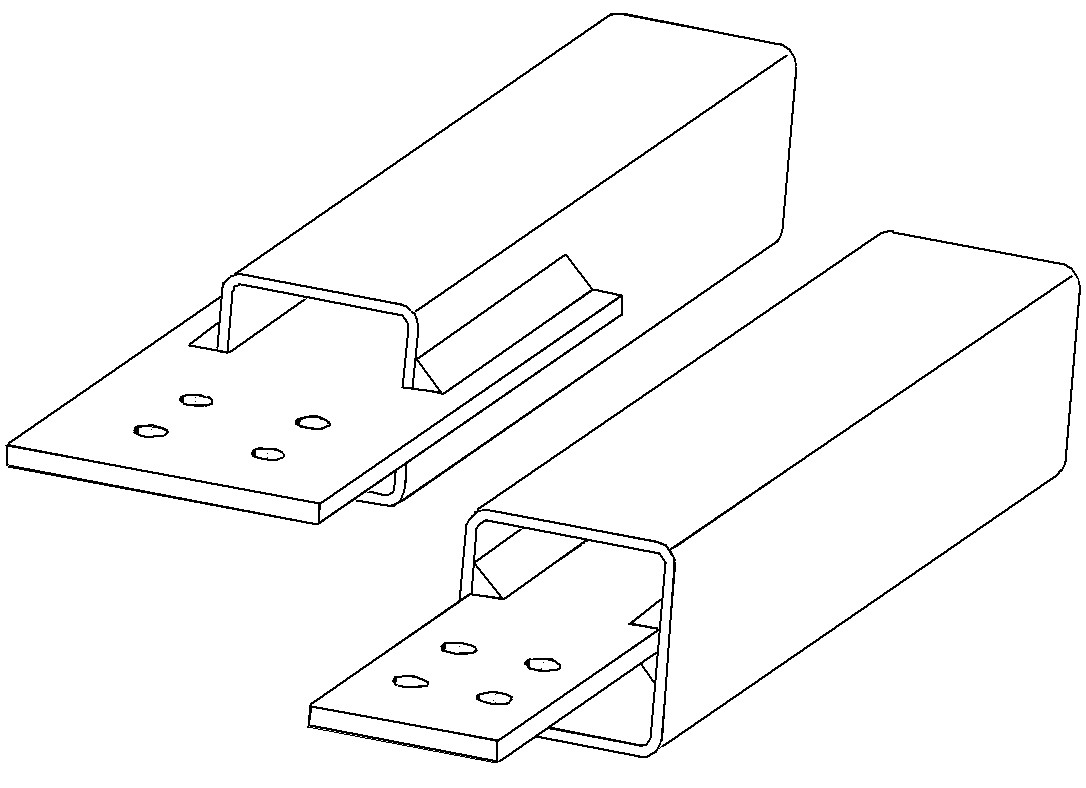
Standard, bolted, splice connections between HSS members are commonly achieved using: (i) a flange plate welded to the end of the member, with the bolts located beyond and around the perimeter of the HSS; or (ii) a plate welded into a slotted HSS, with the bolts located beyond the end of the HSS in a lap splice connection. Case (i) is popular for combined axial force and moment loading combinations, but places the bolts in tension – with the bolt force amplified due to prying action – under axial tension loading in the HSS. Case (ii) is particularly suited to axial loading, places the bolts in shear, but produces shear lag in the HSS as only two walls of the HSS are connected to the inserted plate. Both, however, may be considered unacceptable if aesthetics are important and an architecturally exposed structural steel (AESS) category is sought. AESS is covered in Section 10 of AISC 303-16, the Code of Standard Practice (AISC, 2016a).
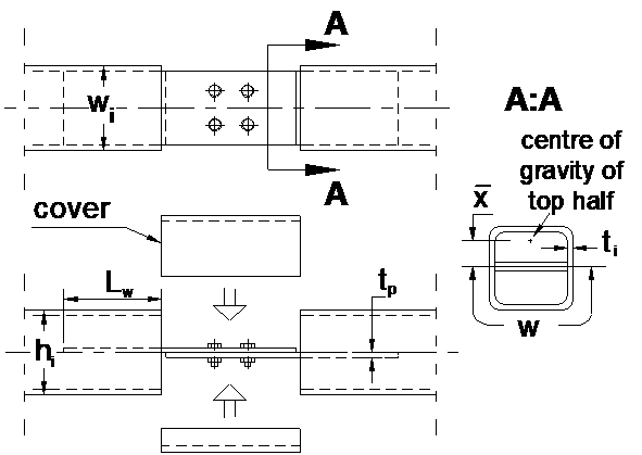
If the need for an invisible bolted splice connection arises, a hidden splice connection may be possible (since there are fabrication and strength limitations) in lieu of the similar slotted HSS lap splice connection (case (ii) above). These two alternates are illustrated in Figure 1. The hidden splice plate connection is also described in STI (2017), as an “interior splice plate” connection. With the plate welded to the inside of the un-slotted HSS, rather than protruding beyond the HSS width, the bolted lap splice can be completely hidden, after bolting up, by a (non-structural) cover in the shape of two half-HSS pieces, as shown in Figure 2. One method for holding the thin cover pieces in place is to use small fasteners through the metal that screw into threaded bars extending from the splice plates. The joint between the cover and the HSS can even be sealed by caulking, giving the appearance of a welded joint. This hidden connection concept can be applied to round, square and rectangular HSS members, but there are member size limitations.
Fabrication
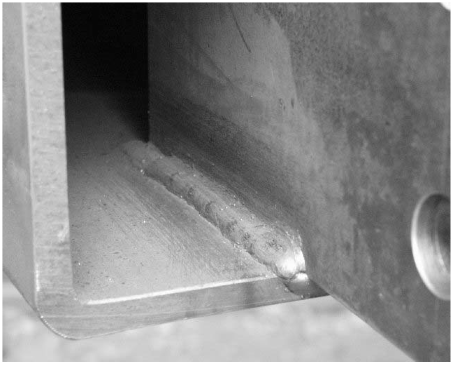
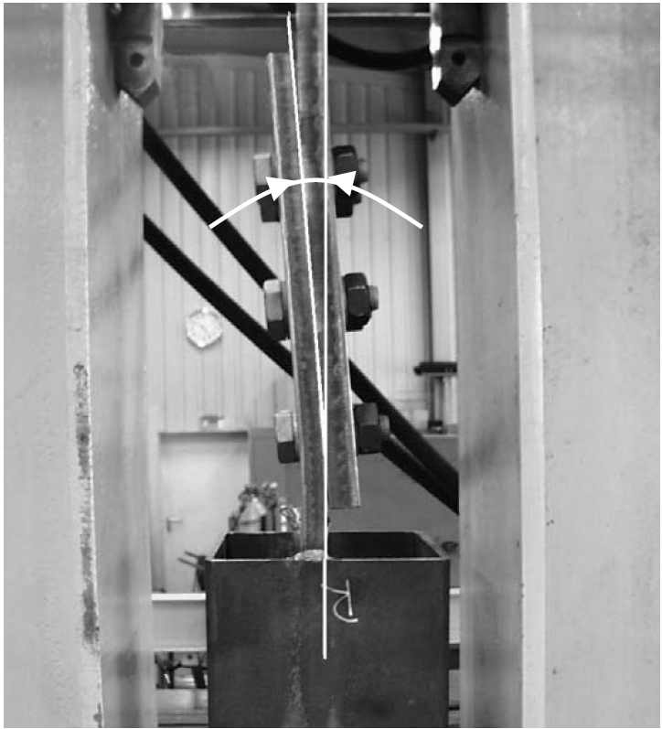
Welding of the inserted plate to the inside of the HSS is achieved by four fillet welds (Figure 3), which will be loaded in shear parallel to the axis of the weld. All welding has to be done from the open end of the HSS and the operating room for the welder is restricted to just half of the HSS void. As a result, it has been found during research on such connections (Willibald et al., 2003a, 2003b) that the maximum weld length possible, inside a square hollow section, is roughly 1.2 times the height of the section (or the arm length of the welder) to avoid a severe loss in welding quality. Given the size of an inserted plate and the access space inside the HSS, welding two plates inside one HSS, in order to maintain a concentrically loaded connection, is not practical. Thus, an eccentrically loaded lap splice connection (as shown in Figure 2) will result, causing bending of the connected plates under load, whether in tension (as shown in Figure 4) or compression. To achieve a concentric lap splice connection, top and bottom lap splice plates would have to be used in the bolted connection to maintain symmetry. Fabrication may also be influenced by interference with the HSS seam weld on the inside of the tube, particularly when the HSS cannot be rotated (e.g. with a plate inserted into a rectangular HSS, in a particular orientation).
Limit States
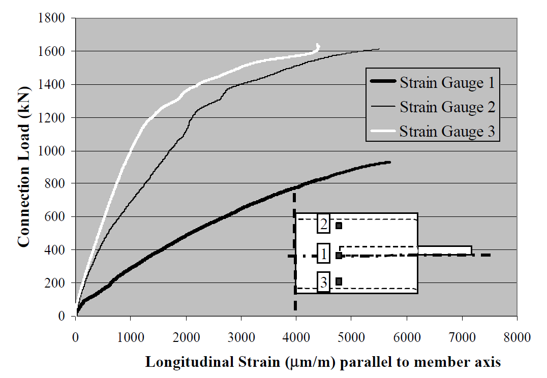
Hidden lap splice connections have analogous failure modes (limit states) to their slotted HSS counterparts. However, restrictions on the plate insertion length and the weld length (to ~ 1.2H) mean that it will be difficult to avoid shear lag occurring in the HSS. At the end of the plate, inserted inside the HSS, the strains in the tube wall next to the plate (where the load is introduced) far exceed the strains in the unattached tube walls, hence the strain in the remote parts of the HSS cross section “lags” that in the attached parts of the cross section. This strain lag is evident in the experimental measurements shown in Figure 5.
When the weld length (l) ≥ 1.3D, for round HSS, Table D3.1 of the Specification (AISC, 2016b) states that the shear lag factor, U = 1 (i.e. there is no shear lag effect). This has been confirmed by Martinez-Saucedo and Packer (2009). Moreover, their research has led to provisions for calculating HSS shear lag in slotted HSS connections (or inserted hidden plate connections) when the weld length, l, is less than D or H.
The following represent the potential limit states (failure modes) of HSS hidden, inserted plate, lap splice connections, under axial loading on the HSS:
For the HSS:
1. Yielding of the HSS (in tension or compression)
2. Circumferential rupture of the HSS at the weld end due to shear lag (in tension)
3. Block shear rupture of the HSS along the welds and across the end of the plate (in tension); shear yielding of the HSS along the welds (in tension or compression)
For the Plate:
4. Yielding of the inserted plate (in tension or compression), along the Whitmore section
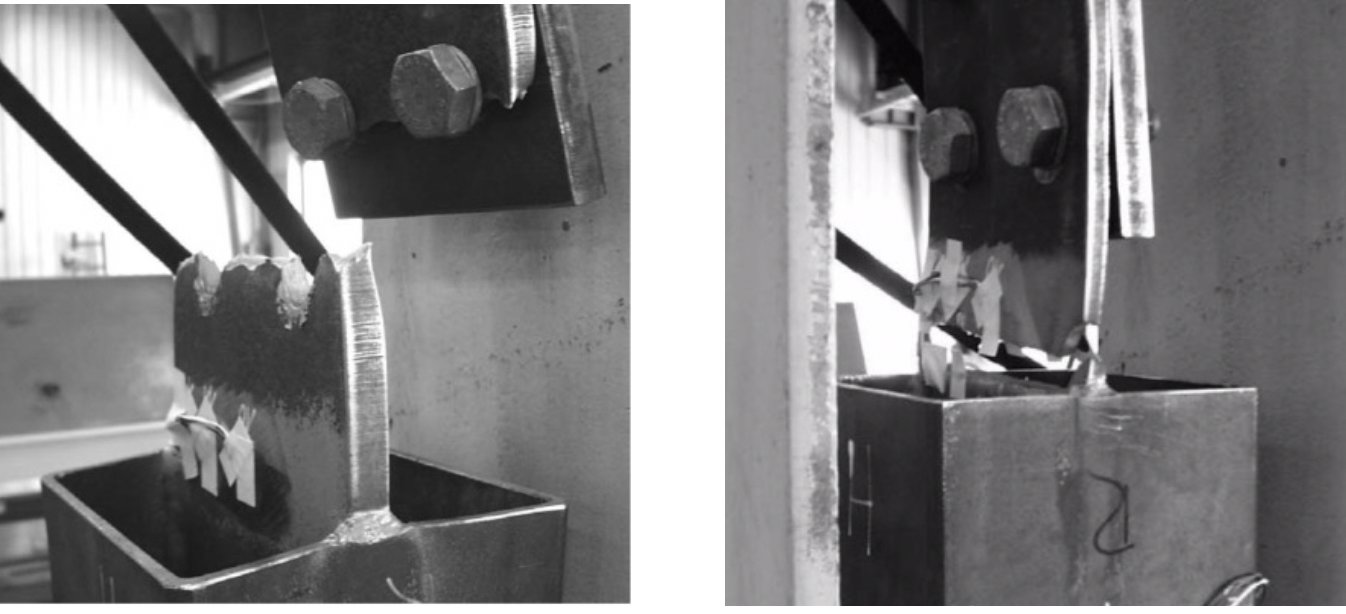
5. Rupture of the inserted plate through the net section (in tension): see Figure 6(a)
6. Rupture of the inserted plate at the weld end due to shear lag (in tension): see Figure 6(b)
7. Block shear rupture around a fracture path through the bolt holes (in tension)
8. Bearing from the bolts (in tension or compression)
9. Buckling of the plate connection, if connected eccentrically to another single plate (in compression): see Figure 4 and Figure 7
For the connectors:
10. Bolt shear failure
11. Weld shear failure

References
AISC. 1997. “Hollow Structural Sections Connections Manual”, American Institute of Steel Construction, Chicago, IL.
AISC. 2016a. “Code of Standard Practice for Steel Buildings and Bridges”, ANSI/AISC 303-16, American Institute of Steel Construction, Chicago, IL.
AISC. 2016b. “Specification for Structural Steel Buildings”, ANSI/AISC 360-16, and Commentary, American Institute of Steel Construction, Chicago, IL.
Martinez-Saucedo, G. and Packer, J.A. 2009. “Static Design Recommendations for Slotted End HSS Connections in Tension”, Journal of Structural Engineering, American Society of Civil Engineers, Vol. 135, No. 7, pp. 797-805.
December 2018