Novel Bolted HSS Splice Connection
by Jeffrey A. Packer
Introduction
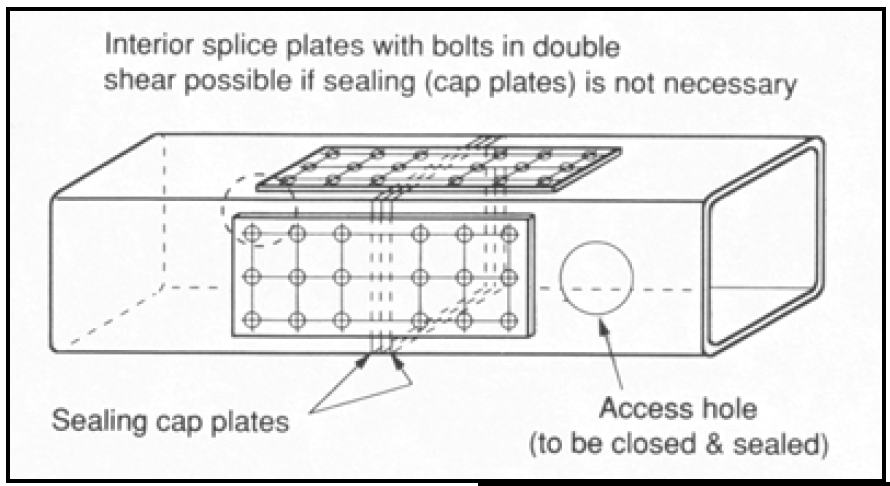
Bolting is the preferred method of joining hollow sections together on site, and two basic methods are available in which: (i) the bolts are loaded in tension, or (ii) the bolts are loaded in shear. With closed sections like HSS it is preferable to use bolts located beyond the periphery of the HSS so that regular high‐strength bolt/nut assemblies can be tightened by normal means. The classic bolted flange‐plate (or end‐plate) connection (Figure 1) is an example of (i) and this has been a common solution for splicing HSS members with either axial tension, axial compression or bending moment acting on the connection. HSS of different outer dimensions can even be joined in this manner. Method (ii), in which the bolts are loaded in shear, is preferable if the connection is subject to any dynamic loading, and some common solutions are shown in Figure 2.

Figure 1: Examples of HSS connections with the bolts beyond the HSS and loaded in tension (from Packer and Henderson, 1997)
Novel Bolted Splice Connection
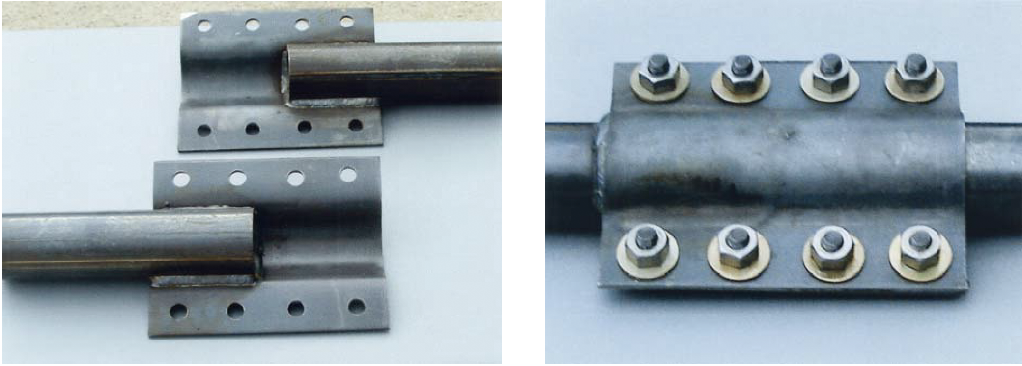
In the two lower examples of Figure 2, gusset plates are shop‐welded to the round, square or rectangular HSS members, projecting outwards from the HSS to be joined, plus additional splice plates are prepared and drilled in the shop, then the connection is bolted together on site. An interesting alternate to this, which avoids the secondary splice plates, is shown in Figures 3 and 4, whereby plates (or “couplers”) are shaped to fit around half the perimeter of each HSS, extending beyond the end of each member and also projecting out from the member, and shop‐welded in place. On site, the two HSS are butted together and the opposing plate projections form a shear connection which can be bolted on site. This unique connection is patented in the U.S. by Gee (2009) and would be an option for relatively small HSS subject to member axial loading. A limited amount of laboratory testing, under axial tension loading, has been performed on this connection, demonstrating that the capacity of the member can be achieved. Further details can be obtained from the inventor: Anthony F. Gee, 6069 Thackeray Drive, Tallahassee, FL 32309; E‐mail: tonygee@tonygee.net


(from Packer and Henderson, 1997)

Figure 3: Gee connection to round HSS or pipe

Figure 4: Gee connection to square/rectangular HSS
References
Gee, A.F. 2009. “Device for Connecting Two Metal Pipes”, United States Patent No. US 7,513,538 B1.
Packer, J. A. and Henderson, J. E. 1997. “Hollow Structural Section Connections and Trusses – A Design Guide”, 2nd. Edition, Canadian Institute of Steel Construction, Toronto, Canada.
February 2013