HSS Base Plate Design for Axial Compression and Bending Moment
By Mike Manor, PE, MLSE
Technical Consultant, Steel Tube Institute
September, 2024
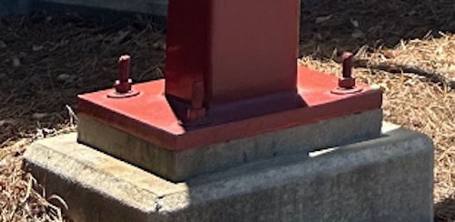
All steel columns need a base plate to transfer the axial and/or flexural forces from the building above into the supporting foundation. Designing base plates for HSS columns is very similar to base plate design for wide flange columns with a few key differences in the specific details. AISC Design Guide 1 Third Edition (AISC DG1) explains the design process for various base plate loadings extremely well for wide flanges, but it only provides a brief paragraph discussion of the design process modifications for HSS. The AISC 16th Edition Manual Companion includes Example K.9 for an axially loaded square HSS column, but current standards do not provide examples for round HSS columns or any HSS columns subject to moment loading. Thus, design examples for HSS base plates are difficult to find. STI provides a great introductory overview of HSS baseplates, “Axially Loaded HSS Column to Base Plate Connections”, which includes a discussion on axial compression loading, axial tensile loading, fabrication, and welding design. To continue the discussion of HSS baseplate design, this article will explore the design of HSS column base plates under axial compression and bending moment.
Geometry
Design of HSS base plates begins with consideration of the geometry and available space for the base plate itself, the supporting foundations, and the anchor rod layout. Anchor rods provide a positive connection to the foundation in cases of uplift, and they must be positioned to allow both adequate space for installation and sufficient concrete cover for the loads present. See Figure 2 for several typical anchor rod layout options specific to HSS columns. For axial compression alone, the location of the anchor rods is not critical in base plate design. However, when uplift or overturning moment exists, the anchor location will play a role in determining the base plate thickness.

Compression Loading
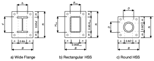
Turning the focus to compression loading of HSS base plates, the main assumption for design is to evenly distribute the compression load under the base plate on the supporting concrete. AISC 360-16 equations J8-1 and J8-2 provide the capacity of the concrete with the second equation accounting for the effects of concrete confinement. The design of the steel base plate is based on the pressure from the total concrete capacity pushing upward on the plate with an even distribution per the AISC 16th Edition Steel Manual (AISC 16th Edition) and AISC DG1. The thickness is then designed for the flexure developed through cantilever action of the plate portion beyond the footprint of the HSS column. The maximum cantilever distance, m or n (See Figure 3 and AISC 16th Edition Equations 14-2 and 14-3), is the distance from end of plate to the critical flexural bending section of the plate and is used to determine the required base plate thickness. Note that the closed shape of HSS columns precludes the need to consider the λn’ distance that is necessary for the open shape of wide flanges where yield lines can form in the area between the flanges and web.
Rectangular HSS columns have two advantages over wide flange columns. First, HSS columns are more efficient for axial loading, resulting in less column steel weight when comparing the capacity at tall unbraced lengths. See the STI HSS and WF Column Selection Guide for more information. Secondly, the coefficient for the critical and cantilever distance equations is 0.95 at rectangular HSS for both orthogonal directions, unlike WF sections which use a 0.8 coefficient for dimension n parallel to the flanges. When comparing WF and HSS with similar nominal dimensions, the smaller cantilever distance means a reduction in the bending moment and thus thinner base plates in many cases for less total steel weight. This can result in a significant tonnage difference in a large building with many columns.
Round HSS is similar to rectangular HSS in that the cantilever coefficients are the same in the two orthogonal directions; however, the coefficient is 0.8 rather than 0.95. The use of these coefficients for HSS is intended to use the same values as wide flange for simplicity while providing a conservative approximation for the distance to the critical bending section.
Uplift Loading
Steel columns can also experience load cases of net uplift over either the entire base plate (axial tension) or on one side only for base plates under large moment (tension component at anchor rods). The tension means that the base plate must be designed for downward flexure which is in the opposite direction than assumed for axial compression as discussed above. The base plate in this case is no longer experiencing an evenly distributed pressure as the load is instead concentrated at the anchor rods. The base plate flexure occurs along either a straight or curved path for rectangular or round HSS respectively.
There are two methods to design the base plate thickness for flexure due to uplift, from which the worst case will control.
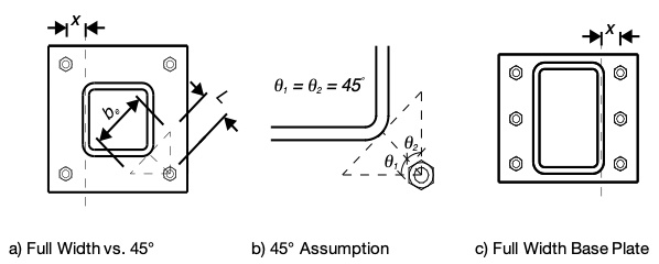
- Check flexure due to the cantilever of the entire base plate beyond the column critical bending section using the entire base plate width with a moment arm equal to the distance 𝑥 in Figure 4a or 4c.
- Check flexure due to a critical bending section located 45° from the column corner. Refer to Figure 4a and 4b. This method is used when the anchor rods are located near the corner of the base plate, which is common for HSS columns. However, the difficult part of this method is determining the location of the flexural failure plane and the associated effective width of the plate. The assumption is that the base plate failure plane occurs at the corner of the HSS. First, start with a line from the anchor rod hole to the corner of the column as the flexural moment arm. Second, the effective width is determined by drawing two more lines from the anchor rod hole 45° each way from the first line until they intersect the assumed failure plane. See the “Designing Column Base Plates for Uplift” article (pp 27-28) in Structure Magazine for an example of this procedure.
Alternatively, a viable option for base plates under tension is the method employed for HSS end plate tension splices. STI has many resources available for this condition of tension loading and similar conditions under flexural loading as well. See the following list of references for connection information and design examples for these alternate methods:
- Round HSS Bolted End-Plate Connections Under Axial Tension Loading
- Round HSS Bolted End-Plate Connections Under Bending Moment
- HSS Design Manual Volume 4 (Bolted Truss End Plate Splice Section)
- AISC Design Guide 24: Hollow Structural Section Connections Second Edition (Ch. 7)
- HSS Poles
HSS Column Base Plate Design Examples
Following are two design examples that demonstrate how to apply the base plate design methodology to HSS columns as presented in AISC Design Guide 1 Third Edition and Part 14 of the AISC 16th Edition Manual. The first example is a round HSS column with only an axial compression load. The second example is a rectangular HSS column with a bending moment combined with an axial compression load to demonstrate the effects of the interaction on the base plate design.
Example #1: Round HSS Column
Given:
- HSS Material: ASTM A500 Gr. C (Fy = 50 ksi)
- HSS 12×0.375 Column
- Base Plate Material: ASTM A572 Gr. 50 (Fy = 50 ksi)
- Factored Axial Load Pu = 500 k
- f‘c = 3 ksi
- Conservatively assume no increase from concrete confinement, thus A1 = A2
HSS Geometry
D = 12 in tnominal = 0.375 in tdesign = 0.349 in
Determine the required base plate area and optimize the base plate dimensions:
![HSS Base Plate Design for Axial Compression and Bending Moment 6 [AISC DG1 Equation 4-6]](https://steeltubeinstitute.org/wp-content/uploads/2024/09/AISC-DG1-Equation-4-6-700w.jpg)
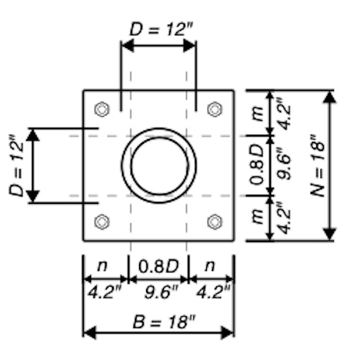
For determining the base plate cantilever distance of round HSS, use 0.8D.

Round up N = B = 18 in
Per assumption given A1 = A2 = NB = (18 in)(18 in) = 324 in2

l = max(m,n) = 4.2 in
(Note: λn‘ is not used for HSS per AISC DG1)

Use 18in x 18in x 1 1/4 in A572 Gr. 50 base plate.
Example #2: Rectangular HSS Column With Bending Moment
Given:
- HSS Material: ASTM A500 Gr. C (Fy = 50 ksi)
- HSS 16x12x1/2 Column
- Base Plate Material: ASTM A572 Gr. 50 (Fy = 50 ksi)
- Factored Axial Load Pu = 376 k
- Factored Moment Load Mu = 300 k ∙ ft = 3600 in ∙ k
- f‘c = 4 ksi
- Conservatively assume no increase from concrete confinement, thus A1 = A2
- Eight anchor rods (4 each side)
HSS Geometry
HHSS = 16 in BHSS = 12 in tnominal = 0.5 in tdesign = 0.465 in
Choose a trial base plate size based on locating anchor rods with dedge = 2″ steel edge distance and 2” clearance from the face of the column for installation, thus 4” beyond the HSS column in each direction.
N = HHSS + (2)(4in) = 24 in
B = BHSS + (2)(4in) = 20 in
Determine the magnitude of the moment relative to the axial load:

![HSS Base Plate Design for Axial Compression and Bending Moment 11 Base Plate with Large Moment [AISC DG1 Figure 4-8]](https://steeltubeinstitute.org/wp-content/uploads/2024/09/Base-Plate-With-Large-Moment-AISC-DG1-Figure-4-8-500w.jpg)
Since e > ecrit’ the loading is considered a large moment, and the assumed baseplate geometry needs to be verified that a solution is possible.

Verify if the following inequality is true

484 ≥ 333 Inequality is true
Determine the length of bearing along the base plate parallel to the moment by solving the quadratic equation:

Since 34.29 in > N and N > 9.71 in > 0, use Y = 9.71 in
The total tension at anchor rods is:
Tu = qmaxY – Pu = (44.2 k/in)(9.71 in) – 376 k = 53.3 k [AISC DG1 Equation 4-55]
Assuming four anchor rods on the tension side, the anchor rods need to be designed for:

Determine the thickness required for the base plate. For cantilever distance of rectangular HSS columns, use a multiplier of 0.95 for both m and n.

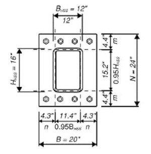
max(m, n) = 4.4 in
(Note: If n was larger than m, n would be substituted in the following)
Y = 9.71 in > m = 4.4 in
(Compression zone extends beyond the base plate cantilever under the column)
Base Plate Yielding Limit at Bearing Interface:

Base Plate Yielding Limit at Tension Interface:

tp(req) = max(1.38 in, 0.73 in) = 1.38 in (Bearing interface controls)
Use 24 in x 20 in x 1 1/2 in A572 Gr. 50 base plate.
Finite Element Analysis
The previous portions of this article provide base plate design information and design examples based on hand calculation methods. However, software packages for steel connections now exist that include finite element analysis (FEA) specifically developed for design by practicing engineers. One option is Idea StatiCa that provides FEA for steel connections in accordance with the AISC Specification. Following is a brief demonstration of the FEA output from Idea StatiCa for comparison with the two examples above (see Figure 5).
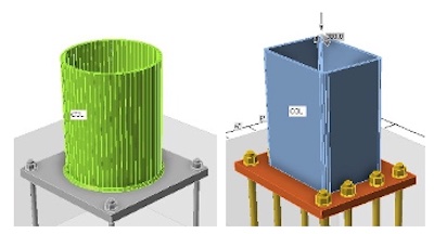
For the calculations above in Example 1, the assumption for a base plate under compression loading with a round HSS column per DG1 guidance is to assume a straight line critical flexural bending section (Figure 3c) based on the diameter of the column. This is a conservative assumption for adapting the rectangular column procedure to the round column shape for ease of hand calculation. However, engineering judgement intuitively would expect more of a circular flexural bending section where the highest base plate stresses would occur. From the FEA, Figure 6a is a map of the base plate stresses showing that indeed the highest stresses develop in a circular pattern. The color-coding scale in Figure 6a was developed by analyzing a 1-1/4” thick 50 ksi base plate as determined by Example 1 and shows a maximum plate stress in the range of 29 ksi. The maximum upper end of the scale comes from applying the AISC 360-16 Section F1 LRFD factor φ = 0.90 to the base plate yield stress: φFy = (0.90)(50 ksi) = 45 ksi. For comparison, the example has a demand capacity ratio (DCR) = t2min/t2 = 1.102/1.252 = 0.77 while the FEA has a DCR = 29 ksi/45 ksi = 0.64 showing the hand calculation to be conservative as expected.
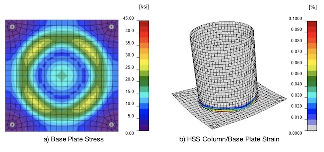
When using FEA for steel connection design, strain is also a calculated measure of connection acceptability. A common general assumption is to allow a maximum 5% plastic strain limit. Figure 6b shows the plastic strain for the round HSS column and base plate. In this example, the maximum strain is only 0.1% < 5%, but it is all located within the column rather than the base plate. For this round HSS example, the FEA demonstrates through both stress and strain that the 1-1/4” base plate is conservative. By maximizing the FEA, Idea StatiCa shows that a 1” A572 Gr. 50 ksi plate is adequate for the loading in Example 1 thus providing a savings for the base plate steel weight.
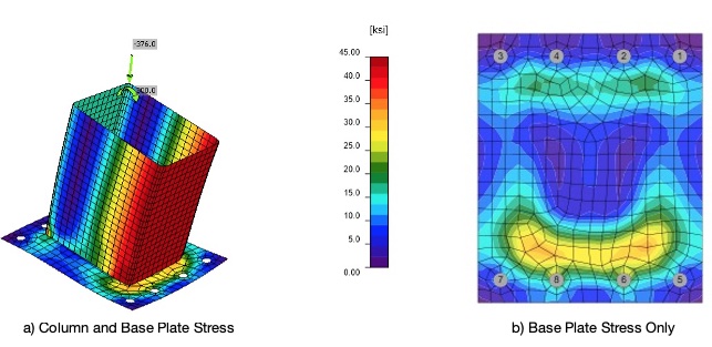
Turning to Example 2, similar comparisons can be made between the hand calculations and the FEA for the rectangular HSS with large moment as shown in Figure 7. Figure 7a indicates that the entire compression flange of the HSS column plus a portion of each sidewall has reached the maximum yield stress and thus some plastic strain. However, looking at Figure 7b, the base plate has a much lower maximum flexural stress in the range of 34 ksi where the corners of the rectangular HSS provide the highest plate compression. Note that the stress in the plate is less than the maximum 45 ksi allowed and thus there is no plastic strain in the base plate. The hand calculated DCR is = t2min/t2 = 1.382/1.52 = 0.85 and the FEA DCR = 34 ksi/45 ksi = 0.76. By again maximizing the FEA, Idea StatiCa determines that a 1-1/4” A572 Gr. 50 ksi base plate is adequate for the loading rather than the 1-1/2” thickness from the hand calculations again providing a steel savings.
Conclusion
While base plate design for HSS members shares similarities with that of wide flange columns, there are key distinctions that engineers must account for, particularly in calculating the cantilever distances for flexural bending. The closed shape of HSS columns, especially rectangular ones, generally results in shorter cantilever distances, which can translate to more economical base plates, particularly in structures with numerous columns. Furthermore, finite element analysis (FEA) software provides valuable tools for optimizing base plate designs, offering a more precise understanding of stress and strain distribution. By leveraging these design resources, engineers can not only ensure structural integrity but also achieve potential savings in steel usage. This efficiency, combined with HSS columns’ performance under axial loads, especially at large unbraced lengths, extends the benefits of HSS members from the column itself to the supporting base plate.
References
- STI Article: “Axially Loaded HSS Column to Base Plate Connections” by Kim Olson
- AISC Publication: “Design Guide 1 Third Edition: Base Connection Design for Steel Structures”
- AISC Publication: “360-22: Specification for Structural Steel Buildings”
- AISC Publication: “Steel Construction Manual 16th Edition”
- AISC/STI/AISI Publication: “Hollow Structural Sections Connection Manual”
- Structure Magazine Article (pp 27-28): “Designing Column Base Plates for Uplift”
- CISC Publication: “Hollow Structural Section Connections and Trusses – A Design Guide”
HSS Reference Guide No. 2: HSS Moment Connections
Explore STI's HSS Moment Connection Reference Guide, to assist you in the design of Beam-to-HSS column and HSS-to-HSS moment connections. The guide features a comprehensive collection of articles, design guides with examples, webinar recordings, and more.