Axially Loaded HSS Column to Base Plate Connections
By Kim Olson, PE
Technical Consultant, Steel Tube Institute
November 2017
Detailing an HSS column to bear on a concrete foundation is one of the most specified connections in a structure. During the fabrication process, the HSS member is typically saw cut to create a flat surface for the member to transfer the structural loads to the base plate. The connection of the HSS to the base plate, usually a weld, depends on the loading and its magnitude. Grout is placed under the base plate to ensure uniform bearing of the plate on the concrete foundation. Anchor bolts are provided to resist the temporary erection loads present during construction as well as the combined shear and uplift forces transferring through the connection due to the structural load requirements of the building.

Axial Compression Loading:
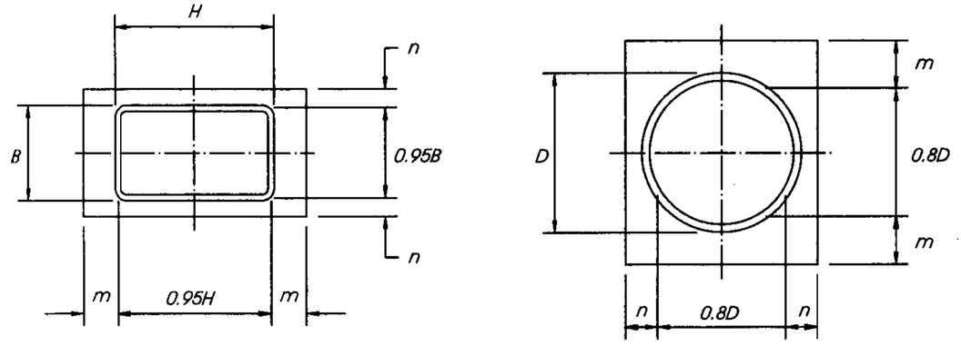
Base plates for round and rectangular HSS columns supporting compressive loads can only be designed using widely accepted provisions developed for wide flange (WF) columns, most notably AISC’s Design Guide 1. This method designs the base plate based on a cantilever projection of the base plate from the walls of the HSS. The location of the critical section is modified for HSS sections (see Figure 2). Design Guide 1 points out that the “m” and “n” distances for round HSS can be determined using a cantilever projection of 0.8 times the outside diameter. For a rectangular HSS, the cantilever projection may be taken as 0.95 times the outside dimension of an HSS. Note that the cantilever projection, λn, which is acceptable for WF columns, cannot be used for HSS columns per AISC Design Guide 1. To decrease base plate deflection, the minimum base plate thickness recommended is approximately one-fifth of the cantilever projection, “m” or “n”. The connection of the HSS to the base plate can be achieved with a minimum all around fillet weld. If the column is in pure compression and the anchor bolts are not located at the corners of the base plate, the fillet weld is required only along the workable flat of the HSS columns. However, if the bolts are located at the corners of the base plate and HSS columns, a weld is required at the HSS corners since the critical yield line will form in the plate at the corners of the HSS.

Axial Tensile Loading:
Researchers have performed a reasonable amount of testing on wide flange columns for the condition of uplift loading to create valid design procedures. Unfortunately, similar procedures for HSS columns are not available. The wide flange procedure cannot be directly transferred to base plates for HSS columns as the connection geometry requires the location of the anchor bolts be different relative to the column. Anchor bolts for WF columns can be placed close to the web, within the depth of the member, thus minimizing the bending moment arm within the plate. In the case of an HSS column base plate, the anchors must be placed a distance away from the column face along the perimeter of the base plate to allow tightening of the anchor bolt nut during installation. If the base plate is not rigid (i.e. thick), the anchor bolts will be subject to prying action which must be accounted for in the design.
Note the AISC Design Guide 1 base plate design procedure for WF columns, if used for HSS columns, would assume a bending plane at the face of the HSS column and the portion of the plate beyond the column as a cantilever. The dimension between the anchor bolt and the bending plane is the moment arm to be used in solving for the base plate thickness. This process uses a wider effective width and smaller moment arm thus results in a thinner base plate which may be unconservative.

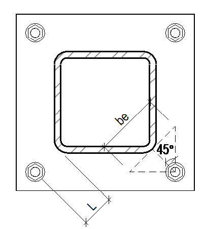
A reasonable approach to designing a base plate for an HSS column under uplift loading is presented here assuming the anchor bolts are placed near each base plate corner (see Figure 3). The challenge in this problem is locating the failure plane and its corresponding effective width. As shown in Figure 3, assume the failure plane is located at the column corner. The effective width is difficult to discern, but one option is to use a 45-degree bending plane for the effective width. Alternately, the AISC Hollow Structural Sections Connections Manual recommends an effective width of 2L with a maximum of 5 inches.
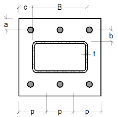
As an alternate layout, the anchor bolts could be arranged on two sides of a rectangular column (see Figure 4). In this case, the base plate can be sized using provisions developed for an end plate connection, again accounting for prying action. Likewise, the end plate design provisions can be used for a round column under uplift with at least four anchor bolts symmetrically placed around the column.

The most economical connection between an HSS column and base plate is a fillet weld. For a tension loaded member where the load is perpendicular to the axis of the weld, the directional strength increase (AISC 360-16, Section J2.4b) should not be employed. Recent testing (Packer, 2016) concluded that when the directional strength increase factor is included in the strength calculation of fillet welds of HSS to base plates, adequate safety factors are not achieved. If a fillet weld is not adequate for the required load, a partial joint penetration weld, either with or without reinforcement, is best. While specifying a complete joint penetration weld may be economical for design, it is anything but economical for fabrication and inspection, thus it should be avoided. Note that the corners of HSS columns must be welded for columns that transfer moment or tension.
References:
AISC, 1990, Steel Design Guide Series 1: Column Base Plates, AISC, Chicago, IL.
AISC, 1997, Hollow Structural Sections Connection Manual, AISC, Chicago, IL.
Mazzei, D., 2012, “Designing Column Base Plates for Uplift,” STRUCTURE Magazine, NCSEA, August, 2012.
Packer, J.A. and Henderson, J.E., 1992, Hollow Structural Section Connections and Trusses, CISC, Willowdale, Ontario, Canada.
Packer, J.A., Sun, M., and Tousignant, K., 2016, “Experimental Evaluation of Design Procedures for Fillet Welds to Hollow Structural Sections,” Journal of Structural Engineering, ASCE, May 2016, Vol. 142, Issue 5.