Round HSS Bolted End-Plate Connections Under Bending Moment
By Jeffrey A. Packer
Bahen/Tanenbaum Professor of Civil Engineering, University of Toronto, Ontario, Canada
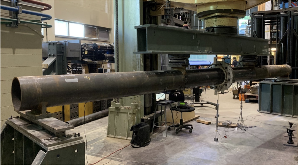
Bolted end-plate connections to round HSS are frequently used in tubular steel structures and typically with circular “blank flange plates” that blank off the end of the tube. Applications in beams, Vierendeel frames, cantilever poles and masts can be cited as situations where this connection is subjected predominantly to bending. Contrary to the axial tension load case, for which there is a well-developed connection design procedure (STI, 2023), under pure bending only a portion of the bolts and the end plate is critically loaded, thus requiring a different connection design approach. The AISC Manual (AISC, 2017) and AISC Design Guide No. 24 (Packer et al., 2010), however, are silent on design methods for this type of bolted HSS connection under predominantly flexural loading. To address this deficiency, large-scale connection tests – between round HSS 12.750×0.500 members with pre-tensioned ASTM F3125 Grade A325 ¾” bolts (ASTM, 2022) – have recently been performed under 4-point bending (Figure 1), which creates a region of constant bending moment in the central connection region. This laboratory phase was then followed by a parametric finite element (FE) numerical study, to cover a wide range of connection parameters, and thus generate an extensive database (Fidalgo and Packer, 2023). The bolting arrangement spaces the bolts uniformly around the tube perimeter.
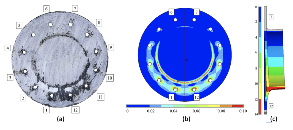
The failure modes or limit states for this connection are end-plate plastification and bolt fracture, or a combination of both. Bolt tensions were monitored during experimental tests (using an ultrasonic bolt gage) as well as during numerical modeling, and it was found that about a third of the bolts (in the extreme tension region) were critically loaded, a third of the bolts (in the compression region) remained at their pre-tension level, and a third of the bolts in between (in the modest tension region) were loaded to increased but non-critical tensions. Connection rotation was observed to take place about an axis aligned with the extreme compression point on the tube, as shown in Figure 2 (where compression is at the top near bolts 6 and 7, and tension is at the bottom near bolts 1 and 12, in the illustrations).
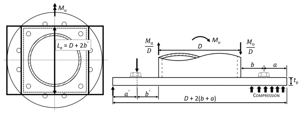
Round HSS are often simplified to equivalent square HSS members for the purpose of producing a simple connection design model, so an equivalent rectangular end plate and square HSS were postulated as shown in Figure 3, with a two-dimensional pattern of linear yield lines. The length of the linear yield lines, (Le) was taken as the tube diameter (D) plus 2b’, where b’ = b – db/2, bis the bolt pitch circle radius minus the tube radius, and db is the bolt diameter. The number of bolts critically loaded in tension (nb’) was taken as 1/3 of the total number of bolts, nb. With this HSS and end-plate conversion performed, a validated T-stub model for rectangular HSS bolted end-plate connections under pure bending by Wheeler et al. (1998) was applied. When evaluated against a database of experimental and numerical circular end-plate bolted connections, this conversion method gave statistically acceptable results (Fidalgo and Packer, 2023).
Design Method
Using expressions for the connection nominal moment capacity by Wheeler at al. (1998), a reliability study was performed to determine resistance factors using a target reliability index of 4.0, which is appropriate for brittle connectors and low-ductility connections, per the AISC 360 Commentary to Section B3 (AISC, 2022). The AISC Manual Part 9 (AISC, 2017) advocates for the use of Fup, the specified minimum ultimate tensile stress of the plate, in prying action models (instead of Fyp, the specified minimum yield stress of the plate), and Thornton (2017) has shown that Fup could be used with design methods for square and rectangular HSS bolted end-plate connections under axial tension loading. By using Fup for the end-plate material strength, a resistance factor of φ = 0.75 was determined and incorporated with the nominal moment capacity expressions. Thus, the connection available moment capacity, Mavailable, for LRFD, will be given by the lesser of Eq. (1) representing the bolt failure limit state, and Eq. (2) representing the end-plate plastification limit state. In addition, the thickness of the end-plate is subject to the limit of applicability of Eq. (3).
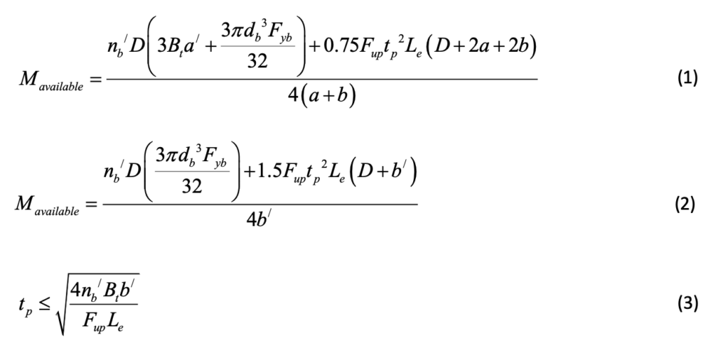
In Eqs. (1) to (3):
| a | = (end-plate diameter – bolt pitch-circle diameter)/2 | (in.) |
| a’ | = a + db/2 | (in.) |
| b | = (bolt pitch-circle diameter – D)/2 | (in.) |
| b’ | b – db/2 | (in.) |
| Bt | = specified minimum tensile strength of one bolt | (kips) |
| db | = bolt diameter | (in.) |
| D | = tube outside diameter | (in.) |
| Fup | = ultimate tensile strength of plate material | (ksi) |
| Fyb | = yield stress of bolt material | (ksi) |
| Le | = yield line equivalent length = D + 2b’ | (in.) |
| nb | = one third of the total number of bolts | (-) |
| tp | = end-plate thickness | (in.) |
Design Example
Two co-axial HSS 6.625 x 0.375 ASTM A500 Gr. C members are joined together by a bolted end-plate connection, as shown in Figure 4, using 6 equally spaced 7/8-in. diameter ASTM F3125 Gr. A325-N bolts. The end-plate thickness is 5/8 in. and the material is ASTM A572 Gr. 50. Determine the available moment capacity of the connection, using LRFD.
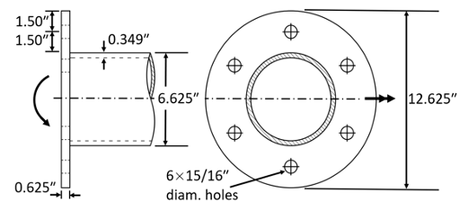
| From the AISC Manual Table 2-5, Fup = 65 ksi for the plate. |
| From the AISC Manual Table 1-13, D = 6.625 in., t (design thickness) = 0.349 in., Z = 13.8 in.3, for the HSS. |
| From the AISC Manual Table 7-2, Bt = (φrn/φ) = 40.6/0.75 = 54.1 kips. Or, alternatively, from AISC 360-22 Table J3.2, Bt = Fnt Abolt = 90 [π(0.875)2/4] = 54.1 kips. |
| From ASTM F3125/F3125M-19 Table 5, Fyb = 92 ksi for A325. |
| From ASTM A500/A500M-21 Table 2, Fy = 50 ksi for round HSS Gr. C. |
| db = 0.875 in. |
| a = b = 1.50 in. a’ = (1.50 + 0.875/2) = 1.9375 in. b’ = (1.50 – 0.875/2) = 1.0625 in. |
| Le = 6.625 + 2(1.0625) = 8.75 in. |
| nb’ = 6/3 = 2 |
- Check that the end-plate thickness is appropriate, relative to the bolt strength:

- Check the bolt spacing and edge distance:
Bolt pitch-circle circumference = π (6.625 + 3.00) = 30.24 in. Therefore, arc spacing per bolt
= 30.24/6 = 5.04 in. Preferred min. spacing = 3db = 3(0.875) = 2.63 in. o.k. AISC Spec. Section J3.3
Min. distance from hole center for 7/8-in. bolt = 1.25 in. ≤ 1.50 in. o.k. AISC Spec. Table J3.4
- Available moment capacity for the limit state of bolt failure:

- Available moment capacity for the limit state of end-plate plastification:

Therefore, Mavailable = 543 kip-in., which represents the maximum value for Mu (Figure 3). As a point of interest, determine the connection available moment capacity as a proportion of the tube design (available) flexural strength.

Thus, the connection available moment capacity is 87% of the HSS member design flexural strength.
References
AISC. 2017. “Steel Construction Manual”, 15th edition, American Institute of Steel Construction, Chicago, IL.
AISC. 2022. “Specification for Structural Steel Buildings”, ANSI/AISC 360–22, American Institute of Steel Construction, Chicago, IL.
ASTM. 2022. “Standard Specification for High Strength Structural Bolts and Assemblies, Steel and Alloy Steel, Heat Treated, Inch Dimensions 120 ksi and 150 ksi Minimum Tensile Strength, and Metric Dimensions 830 MPa and 1040 MPa Minimum Tensile Strength”, F3125/F3125M–22, American Society for Testing and Materials, West Conshohocken, PA.
ASTM. 2021. “Standard Specification for Cold-Formed Welded and Seamless Carbon Steel Structural Tubing in Rounds and Shapes”, A500/A500M–21a, American Society for Testing and Materials, West Conshohocken, PA.
Fidalgo, A. and Packer, J.A. 2023. “Bolted CHS Flange-Plate Connections under Bending”, Journal of Structural Engineering, American Society of Civil Engineers, Vol. 149(6), 04023066-1 – 15.
Packer, J.A., Sherman, D. and Lecce, M. 2010. “Hollow Structural Section Connections”, Steel Design Guide No. 24, American Institute of Steel Construction, Chicago, IL.
STI. 2023. “Round HSS Bolted End-Plate Connections under Axial Tension Loading”, Technical Article, Steel Tube Institute.
Thornton, W.A. 2017. “Yield Line Approaches for Design of End Plate Tension Connections for Square and Rectangular HSS Members using End Plate Tensile Strength”, Engineering Journal, Vol. 54, No. 3, pp. 141 – 154.
Wheeler, A.T., Clarke, M.J., Hancock, G.J. and Murray, T.M. 1998. “Design Model for Bolted Moment End Plate Connections Joining Rectangular Hollow Sections”, Journal of Structural Engineering, American Society of Civil Engineers, Vol. 124, No. 2, pp. 164 – 173.
August 2023
Allianz Field – A Modern Stadium Marvel in St. Paul
The Allianz Field stadium cuts a striking image across the St. Paul, Minnesota, skyline. However, a dynamic structure like this isn’t built overnight or without thoughtful consideration. Discover how HSS and innovative design helped this beautiful building come to life.