Round HSS Bolted End-Plate Connections under Axial Tension Loading
By Jeffrey A. Packer
Bahen/Tanenbaum Professor of Civil Engineering, University of Toronto, Ontario, Canada

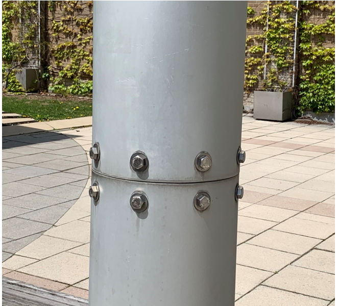
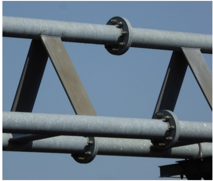
Figure 1: Round HSS bolted splice connections
Splicing HSS members together using a bolted connection is favored over a fully welded connection, as site bolting is a far simpler and more economical solution. Bolting through the HSS wall, as shown in Figure 1(a), causes a reduced net area because of the bolt holes and results in a member tensile capacity that is less than the HSS yield strength. Consequently, bolting outside the HSS is a popular way of developing the full member strength. For round HSS, a circular end-plate (or flange-plate) connection with the bolts evenly distributed around the tube is a popular option (Figure 1(b)), particularly for long-span trusses. This article provides an updated overview of the design methods that are now available for this type of bolted connection, between round HSS, using “blank flange plates” (which blank off the end of the tube, and hence do not ring the tube) and subject to static axial tension loading.
Japanese Method

Figure 1: Round HSS bolted splice connections
Igarashi et al. (1985) have proposed a relatively straightforward design approach, based on the yield-line method, which assumes that prying forces are always present, act at the edge of the plate and amount to a third of the total bolt force at the ultimate limit state. This method has gained considerable international acceptance, and has been recommended in design guides by CISC (Packer and Henderson, 1997), AIJ (2002), CIDECT (Wardenier et al., 2008), and AISC (Packer et al., 2010). Providing the weld develops the yield strength of the connected tube wall, two failure modes (limit states) are possible for such connections: end-plate plastification and bolt fracture. The nominal tensile strength of the connection, Pn, for these limit states is given by Eqs. (1) and (2), respectively:

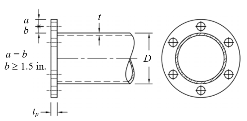
where Fyp is the specified minimum yield stress of the plate, tp is the plate thickness, nb is the number of bolts, Bt is the specified minimum ultimate strength of one bolt, r1 = 0.5D + 2b, and r2 = 0.5D + b (see Figure 2). Note that the design procedure is for standardized connections in which a = b. The dimensionless geometry factor f3 is given by:

where k1 = ln(r2/r3), r3 = (D – t)/2 (see Figure 2), and k3 = k1 + 2.

For LRFD implementation of Eqs. (1) and (2), resistance factors need to be applied in order to obtain the connection available strength. Thus, in accordance with the AISC 360 Specification Section J10 (AISC, 2022), a value of φ = 0.9 would be applied to Fyp in Eq. (1) for local bending action. Also, in accordance with the AISC 360 Specification Section J3.6, a value of φ = 0.75 would be applied to Bt in Eq. (2) to obtain the bolt available tensile strength.
Recently, a reliability study has been performed on this design method using all available experimental and numerical data for this connection type published in research literature (Fidalgo and Packer, 2022). A common target reliability index of 4.0, which is appropriate for brittle connectors and low-ductility connections (AISC 360 Commentary to Section B3), was applied to both Eqs. (1) and (2). This reliability study showed that a resistance factor of φ = 0.9 was suitable for the overall design method, and hence could be applied to both Eq. (1) for Fyp, and to Eq. (2) for Bt. This is more liberal than the implementation of this method at present, because φ = 0.75 is currently applied to Bt by default.
The AISC Manual Part 9(AISC, 2017) advocates for the use of Fup, the specified minimum ultimate tensile stress of the plate, in prying action models (instead of Fyp) as it … “provides better correlation with available test data than previous design methods”. Thornton (2017) showed that Fup could even be used with design methods for square and rectangular HSS bolted end-plate connections under axial tension loading. Fidalgo and Packer (2022) thus investigated the possibility of using Fup in Eq. (1), in lieu of Fyp. Maintaining the same target safety index of 4.0, it was found that a common resistance factor of φ = 0.75 was applicable for Eqs. (1) and (2). While this would seem uncontroversial for Bt in Eq. (2), it is a tradeoff for using Fup in Eq. (1).
T-Stub Analogy Method
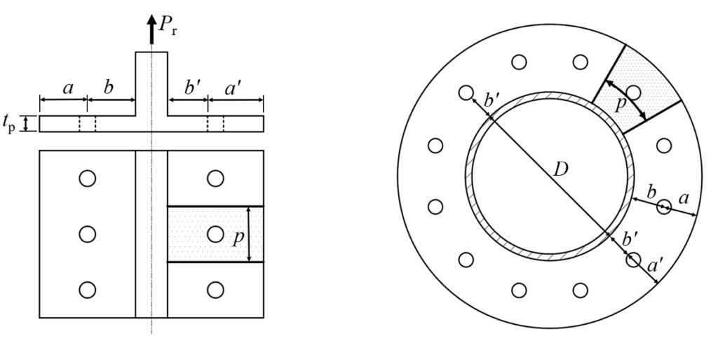
The two-dimensional T-stub prying model of Struik and de Back (1969) has been used world-wide by engineers for over 50 years. An adaptation of this model was possible for handling the three-dimensional prying situation of a rectangular HSS bolted end-plate connection under axial tension loading (Willibald et al., 2002, 2003), so an attempt was made to adapt the classic T-stub prying model (Figure 3(a)) to round HSS bolted end-plate connections under axial tension (Fidalgo and Packer, 2022). A plate tributary width, p, with respect to one bolt, was taken along the bolt pitch circle – but shifted towards the tube by half a bolt diameter (Figure 3(b)), per the modified Struik and de Back (1969) model and also as done in the AISC Manual, Figure 9-4(c) (AISC, 2017), which is shown in Figure 3(a). This results in a tributary length, per bolt pair, of:

where b/ = b – db/2, and db is the bolt diameter.

Using the “adapted representation” in Figure 3(b), one can follow the procedure for 2D T-stub prying action analysis in Part 9 of the Manual (AISC, 2017), for “when the fitting geometry is known”, using Eqs. (9-27) and (9-28). Correlation with available data showed an improved Mean and Coefficient of Variation (CoV) for the ratio of (Actual connection strength)/(Predicted connection strength) relative to the Japanese method (Igarashi et al., 1985; AIJ, 2002). By again using a target reliability index of 4.0, a reliability study was performed for this T-stub analogy method (Fidalgo and Packer, 2022). This showed that, if one used Fyp for the plate material strength, a resistance factor of φ = 0.9 was suitable for the overall design method, and hence could be applied to Fyp as well as the bolt ultimate tensile strength.
However, if Fup is used in this design procedure in lieu of Fyp – as done already in the Manual (AISC, 2017) – then φ = 0.75 is required for both the bolts (as already used) and the material strength term (Fup). The Manual currently applies φ = 0.9 to Fup. Thus, this “adaptation” for p in Eq. (4) does not provide sufficient structural safety/reliability if applied directly to the method in the AISC Manual Part 9.
Recommendation
In order to use the Igarashi et al. (1985) method, as adopted in AISC DG24 (Packer et al., 2010), yet use the ultimate stress of the end-plate material, as advocated in the AISC Manual (AISC, 2017), the connection available strength for LRFD will be given by the lesser of:

where Bc = φBt is the design (available) tensile strength of one bolt, per AISC 360 Specification Section J3.6 (AISC, 2022). Other variables are as defined previously. Since (φ=0.75)Fup in Eq. (5) > (φ=0.9)Fyp , for both ASTM A36 and ASTM A572 Gr. 50 plate steel, the available connection strength by Eq. (5) is actually greater than that currently in AISC DG24, which uses Eq. (1) with φ = 0.9.
Design Example
Determine the end-plate thickness and the number of bolts needed by LRFD, to resist a required tensile strength of Pu = 150 kips acting on a HSS 6.625 x 0.375 ASTM A500 Gr. C section. The end-plate material is ASTM A572 Gr. 50 and the bolts are 7/8-in. diameter ASTM F3125 Gr. A325-N. Assume that the tube-to-plate weld develops the HSS wall yield strength, which is a requirement of this design method. Set a = b = 1.5 in. (see Figure 2).
From the AISC Manual Table 2-5, Fyp = 50 ksi and Fup = 65 ksi for the plate.
From the AISC Manual Table 1-13, D = 6.625 in. and t = 0.349 in. for the HSS.
From “Japanese Method” above: r1 = 0.5D +2b = 0.5(6.625) + 2(1.5) = 6.313 in.
r2 = 0.5D + b = 0.5(6.625) + 1.5 = 4.813 in.
r3 = (D – t)/2 = (6.625 – 0.349)/2 = 3.138 in.
k1 = ln(r2/r3) = ln(4.813/3.138) = 0.428
k3 = k1 + 2 = 2.428
Setting Pavailable from Eq. (5) ≥ Pu and re-arranging,

Setting Pavailable from Eq. (6) ≥ Pu and re-arranging,

where Bc = φrn = design (available) tensile strength of one bolt = 40.6 kips, from AISC Manual Table 7-2.
Thus,

Hence use 6 bolts. Check that the bolt spacing, s, around the bolt circle, is acceptable.

From the AISC 360 Specification Section J3.3, the preferred minimum spacing = 3 x (bolt diameter) = 3(7/8) = 2.63 in. The actual spacing (5.04 in.) > 2.63 in., so the bolt spacing is acceptable. Also, note that AISC 360 Specification Table J3.4 stipulates a minimum edge distance from the hole center to the edge of the plate = a (Figure 2). For a 7/8-in. diameter bolt, the minimum edge distance is 1.25 in. The actual edge distance, a = 1.5 in., is therefore acceptable.
References
AIJ. 2002. “Recommendations for the Design and Fabrication of Tubular Truss Structures in Steel”, Architectural Institute of Japan, Tokyo, Japan.
AISC. 2022. “Specification for Structural Steel Buildings”, ANSI/AISC 360-22, American Institute of Steel Construction, Chicago, IL.
AISC. 2017. “Steel Construction Manual”, 15th edition, American Institute of Steel Construction, Chicago, IL.
Fidalgo, A. and Packer, J.A. 2022. “Evaluation of Bolted CHS Flange-Plate Connections under Axial Tension”, Journal of Constructional Steel Research, Vol. 196, 107399.
Igarashi, S., Wakiyama, K., Inoue, K., Matsumoto, T. and Murase, Y. 1985. “Limit Design of High Strength Bolted Tube Flange Joint – Part 1: Joint without Rib Plates and Ring Stiffener”, Journal of Structural and Construction Engineering Transactions of AIJ, Vol. 354, pp. 52 – 66.
Packer, J.A. and Henderson, J.E. 1997. “Hollow Structural Section Connections and Trusses – A Design Guide”, 2nd edition, Canadian Institute of Steel Construction, Toronto, ON.
Packer, J.A., Sherman, D. and Lecce, M. 2010. “Hollow Structural Section Connections”, Steel Design Guide No. 24, American Institute of Steel Construction, Chicago, IL.
Struik, J.H.A. and de Back, J. 1969. “Tests on High Strength Bolted T-Stubs with Respect to a Bolted Beam to Column Connection”, Report No. 6-69-13, Stevin Laboratory, Department of Civil Engineering, Delft University of Technology, Delft, The Netherlands.
Thornton, W.A. 2017. “Yield Line Approaches for Design of End Plate Tension Connections for Square and Rectangular HSS Members using End Plate Tensile Strength”, Engineering Journal, Vol. 54, No. 3, pp. 141 – 154.
Wardenier, J., Kurobane, Y., Packer, J.A., van der Vegte, G.J. and Zhao, X.-L. 2008. “Design Guide for Circular Hollow Section (CHS) Joints under Predominantly Static Loading”, CIDECT Design Guide No. 1, 2nd edition, Comité International pour le Développement et l’Étude de la Construction Tubulaire, Geneva, Switzerland.
Willibald, S., Packer, J.A. and Puthli, R.S. 2002. “Experimental Study of Bolted HSS Flange-Plate Connections in Axial Tension”, Journal of Structural Engineering, American Society of Civil Engineers, Vol. 128, No. 3, pp. 328 – 336.
Willibald, S., Packer, J.A. and Puthli, R.S. 2003. “Design Recommendations for Bolted Rectangular HSS Flange-Plate Connections in Axial Tension”, Engineering Journal, American Institute of Steel Construction, Vol. 40, No. 1, pp. 15 – 24.
January 2023
The View From Over Here: Teaching and Exploring Structural Engineering Practices From Around the World
Gian Andrea Rassati, associate professor at the University of Cincinnati, shares his perspectives on bolted HSS connections, and m…
Webinars On Demand: Bolting to HSS
This free webinar teaches various bolting techniques for HSS connections, gives details and design examples and more.
Hidden Bolted HSS Splices
Learn techniques tools, and aesthetic benefits you can achieve when using hidden bolted splice connections between HSS members.