Expert Tips for Cost-Effective HSS Specification and Fabrication
By Mike Manor, PE, MLSE and Cathleen Jacinto, PE, SE
Technical Consultants, Steel Tube Institute
Hollow Structural Sections (HSS) are an increasingly popular choice in structural steel design. They offer superior strength-to-weight ratios, and their smooth and uniform appearance make them an attractive option for architectural application. However, when appropriate considerations are not taken, fabrication can be challenging and expensive.
We spoke with 11 fabricators and bender rollers* to discover what real-world challenges they have in fabricating HSS, and how this impacts project cost. Although each fabrication shop has its preferences, we were able to draw from these insightful discussions to arrive at the expert tips summarized below. We will explore details that add to HSS fabrication cost and learn how to detail your HSS connections to be more efficient and cost effective for the fabrication process. Scroll to the end of this article for a handy table of Wide Flange (WF) to HSS connection options, identified as low, medium, or high cost by fabricators we surveyed.
HSS Sizes and Shapes
- Refer to the STI Capability Tool to check availability of HSS sections. Not every HSS size in the AISC Manual is readily available in the domestic market. Refer to the STI article on Round HSS Availability which summarizes round HSS sections that are widely produced domestically.
- Round HSS should be specified as ASTM A500 for structural members, not A53 pipe. For discussion and a table of equivalent pipe to round HSS sections, see the following STI article.
- It is typically easier to procure large quantities of the same HSS size rather than smaller quantities of different sizes.
- Be aware of the potential need to accommodate tolerances in HSS connections, i.e. shims.
- Bowing can occur in square/rectangular HSS, and this may impact alignment in end-to-end connections or in-framing connections.
- The larger the HSS shape, the larger the permissible tolerances.
- Refer to the STI Tolerance Guide for a summary of permissible A500 tolerances.
HSS Column Splices
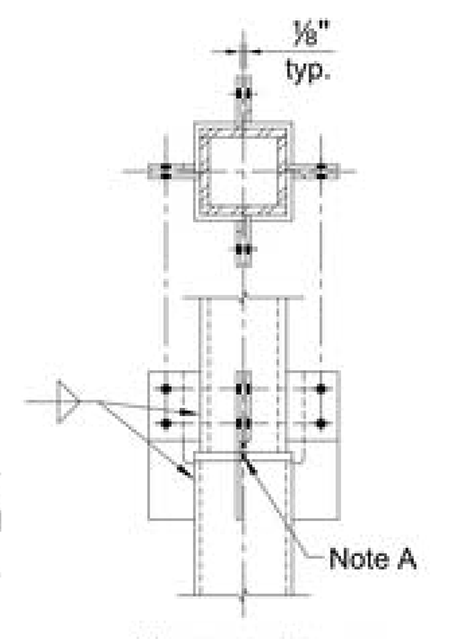
- Avoid directly-welded Complete Joint Penetration (CJP) HSS column splices, where possible. See the welding section below for discussion on CJP welds.
- For a directly-welded connection, the suggested splice is a Partial Joint Penetration (PJP) weld showing the effective throat required, and bolted alignment plates for erection aids.
- When splicing two different HSS sizes, a butt-plated splice is ideal. Refer to Figure 2 for an example of this.
- Other cost effective HSS splice options are the bolted end plate connection as well as the bolted splice plate connection with access holes. Refer to Figures 3 and 4.
When directly welding two HSS members of the same size with CJP welds, alignment issues can arise. In particular, if HSS members of the same size are procured from different producers with different corner radii, it can be a challenge to align and prep for CJP welds. This is especially true for larger-sized tubes, which have larger radii in the corners. It can take many weld passes to fill a flare bevel CJP weld joint flush with the tube face, if required. Therefore, it is suggested to avoid directly-welded CJP HSS column splices.
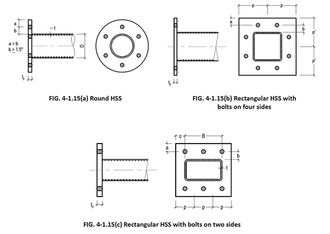
STI Manual Vol 4 Fig. 4-1.15
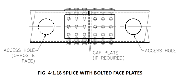
STI Manual Vol 4 Fig. 4-1.18
Cap/End Plates
- HSS cap plates are generally not a challenge to fabricate.
- For a cap plate intended only to seal the end of the HSS member, size the cap plate to be slightly smaller than the column to allow for a fillet or PJP weld.
- However, if the cap plate is intended to transfer loads in a connection, ensure the cap plate size extends adequately to transfer load. Refer to the STI article on Cap Plate Connections for additional information.
- For square or rectangular HSS welded to an end plate or base plate, specify fillet or PJP welds on the workable flats only. Avoid welding the corners for a cost-effective connection, and when not required to transfer connection forces.
- CJP welds require UT inspection and it is difficult to pass inspection for CJP welds at HSS corners, increasing risk of weld rejection.
Slotting Plates Into HSS
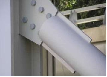
Image Credit: Atlas Tube
- At shear connections, it is likely more cost-effective to increase the HSS wall thickness to allow for a face-welded connection in lieu of slotting the HSS, where possible.
- At HSS brace or truss diagonal connections, slotted connections are often provided at the end of the HSS per Figure 5. In some conditions, slotted connections to gusset plates are more cost-effective than an all-welded truss connection. The slot is detailed to be 1/16” to 1/8” larger than the slotted plate thickness and length. Keep this in mind when checking the HSS for shear lag and net area. See the STI article on Shear Lag in Slotted End HSS Connections for additional information.
Moment Connections
- Most fabricators cite the through-plate moment connection as the most expensive HSS connection (see Figure 6). This requires cutting or splicing the HSS column at the connection.
- For alternate fully restrained moment connections, consider the following:
- Welded Tee Flange moment connection (Figure 7)
- The WT welded to the face of the HSS also engages the HSS sidewalls in resisting rotation. Coordinate with any in-framing connections.
- Cut-out / collared flange plate moment connection (Figure 8)
- Welded Tee Flange moment connection (Figure 7)
- Flange-plated or directly welded flanges to the HSS column are another cost-effective option (Figure 9). This is a partially restrained (PR) moment connection and one must consider greater connection rotation due to the flexibility of the HSS wall.
- It is suggested to increase the HSS wall thickness if this allows the face-welded connection to work, in lieu of a through-plate moment connection.
- Refer to the following STI article for additional alternate moment connections and the STI Manual Vol 3 for design examples.
The through-plate moment connection typically requires cutting the HSS column into three pieces, and then reassembling it by welding it to the through plates (See Figure 6). Cutting the HSS column, reassembling, and CJP welding the through plates all mean extra labor time.
Before specifying through-plate moment connections, consider connections that do not require cutting the HSS column. The most cost-effective moment connection is a continuous beam over HSS column connection (see Figure 10). Alternately, WTs at the top and bottom of the beam flanges welded to the HSS column is also a more cost-effective option (see Figure 7). The WT connection engages both the HSS face and sidewalls to resist moment. Flange plated moment connections to the HSS column are also an option which utilizes flange plates top and bottom of the beam. One caveat is to consider the effect of semi-rigid behavior with face-welded HSS moment connections.
Lastly, most fabricators agree that it is better to upsize the HSS wall (if needed) to transfer moment in lieu of providing a through-plate connection. HSS Connex is a helpful tool to check the adequacy of the HSS wall in a flange-plated moment connection, by utilizing the transverse plate option in the program. To summarize, more cutting = more fabrication complexity, so it is best to avoid through-plate moment connections.
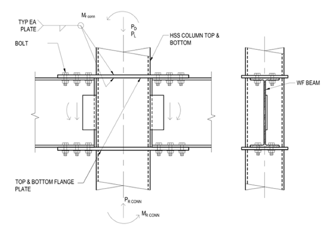
STI Manual Vol 3 Fig. 3-17
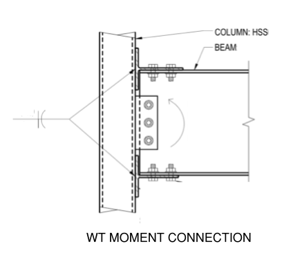
STI Manual Vol 3
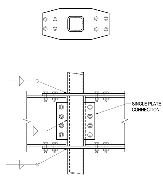
STI Manual Vol 3 Example 3-7.3
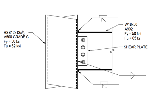
STI Manual Vol 3 Example 3-7.5
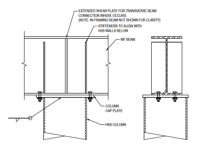
STI Manual Vol 3 Fig. 3-16
Welding To HSS
- Avoid defaulting to CJP welds, and instead design fillet or PJP welds to HSS.
- Where PJP welds may not suffice, consider a fillet-reinforced PJP weld.
- Where flare bevel PJP welds are needed at the HSS corners, show the effective throat size required. The weld may not need to be filled flush.
- When abutting two HSS members end-to-end and directly welding, do not detail a butt weld. Instead, specify a PJP bevel weld.
- A butt weld is a CJP weld requiring backer bars. A PJP bevel weld requires prep only from one side and no backer bars.
Complete Joint Penetration (CJP) – CJP welds require backing bars on the opposite steel face from the weld. The closed shape of HSS makes this difficult to install, and in seismic detailing, these backer bars are often required to be removed, which is not feasible after the connection has been completed. CJP welds also trigger UT inspection requirements. Passing UT inspection can be difficult at corners, tight branch angles, etc, risking weld rejection. Before specifying a default CJP weld, it is best to design fillet and PJP welds for actual forces, ensuring that the effective throat is shown.
Partial Joint Penetration (PJP) – For HSS connections, PJP welds are often flare bevel groove welds at rectangular and square corner radii. Fabricators note that PJP welds are much more cost-effective than CJP welds; however, the effective throat is often missing in details. When this is the case, welders will typically fill the bevel flush, resulting in additional fabrication time and cost. Therefore, it is recommended to specify the required PJP throat size.
HSS Truss Connections
- In welded truss joints, the HSS branch-to-chord acute angle should be a minimum of 30 degrees to allow access for welding.
- At branch-to-chord connections, specify the weld length required rather than specifying to weld all-around. Even at acute angles of 30 degrees, it is difficult to weld all around.
- Gapped K-connections are more cost-effective than overlapped K-connections. Overlapped K-connections require a double miter cut on the overlapping branch, which requires a good deal of preparation. Gapped K-connections with fillet welds at the branch-to-chord connection are ideal for fabrication.
In a welded truss connection, a very tight acute angle may result in a non-prequalified weld. This requires the fabricator to develop a weld procedure and perform qualification reports and testing. This involved process may ultimately result in an unsuccessful weld. Therefore, it is best to lay out the truss geometry considering weld access.
Curving HSS
- Most bender rollers agree it is best to leave the bending process (hot or cold) for the fabrication team to decide as ‘means and methods.’ Every bender roller is different, and capabilities vary. See below for more information.
- Bender rollers recommend specifying desired tolerances (i.e. max or min HSS section dimensions) after bending. Ensure design is based on the potentially reduced HSS geometric properties. See below for more information.
- Nominal dimensions could change as a result of the bending process.
- AISC Design Guide 33 on Curved Member Design is a helpful resource to address potential distortions.
- Specify single radius curves, where possible.
- Reach out to bender rollers to confirm HSS sections feasible for a given bending radius.
Refer to this STI article, “HSS Bending of Hollow Structural Sections,” for additional information on the bending process for HSS. There are generally two types of bending processes to curving HSS: cold bending and hot bending. Hot bending generally has the best finished result but is a very slow process that is significantly more expensive than cold bending. Cold bending is used more often unless it is not possible for the configuration. It is best not to specify the process to use to allow the bender to choose the best process for the project. Instead, the recommendation is to specify tolerances. Bending HSS is likely to result in distortions to the steel member to some degree since it brings permanent plastic deformation into the steel shape. Controlled distortion is part of a successful bending process. In general, larger HSS sizes are more difficult to bend and also more difficult to maintain their geometric shape. For example, a 20-inch diameter HSS may only have an outside diameter of 19 inches after completion of the bending process, so the design of the member needs to be based on the reduced geometric section properties. Therefore, bender rollers recommend that designers specify max or min HSS dimensions to meet design criteria.
Every bender roller is different, and capabilities vary. When determining the feasibility of bending for a design, it is recommended to reach out to benders to get a consensus on the HSS shape, size and thickness that will provide the best result for a given bending radius. Contact STI and we can point you to bender rollers to assist you.
Relative Cost of WF to HSS Connection Types
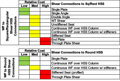
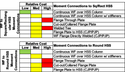
To assist designers in understanding the relative costs of various WF beam to HSS column connection types, we have provided Tables 1 and 2. Fabricators have classified these WF beam to column connections into three categories based on their fabrication cost: low, medium, and high. Most moment connection details are shown above. For shear connection details, see the following STI article. Note that WF beams are referenced in these tables, however HSS beams are an option as well. STI Manual Vol. 3 contains discussion and examples for HSS beam to HSS column connections.
Note that a few connection types show more than one cost category. This is due to varied responses from different fabricators spoken to, and to highlight which connections surveyed were borderline in cost.
*Thank you to the following fabricators who contributed to this article and shared their valuable, real-world fabrication insight:
- American Structural Metals, Inc (ASM-MMF) – Mitch Ortner
- Chicago Metal Rolled Products – Ken Pecho, Sales/Project Engineer & Technical Operations
- Drake-Williams Steel –
- Maryann Davis, Estimating Manager
- Scott Van Deren, Business Development
- Eric Bradbury, AWS CWI / QA Supervisor
- Russell Reichenberg, Riley Caples, Abraham Rodriguez
- The Gateway Company – Craig Wehrmann, General Manager
- Max Weiss Co., LLC – Alan Sanders, President
- Merrill Steel – Fred Schwalbach, President, and Andrew Huebner, Vice President – Sales & Estimating
- Metal Works – Jesse Bessmer, Director of Project Management and Quality Assurance
- Patriot Erectors, LLC – Neil Glaser, Chief Engineer
- Puma Steel – Wade Lewis, Vice President
- STS Steel – Glenn Tabolt, Chief Executive Officer, and Geoff Frazier, President
- W&W | Afco Steel – Kevin Reynolds, Executive Vice President
April 2023
Insights from a Steel Fabricator
Our team was able to meet with Jesse Bessmer, director of project management and quality assurance at Metal Works, to discuss his opinions on overcoming HSS challenges from a fabricator’s perspective.