Welding in HSS Corners
By Jeffrey A. Packer
Bahen/Tanenbaum Professor of Civil Engineering, University of Toronto, Ontario, Canada
March 2022
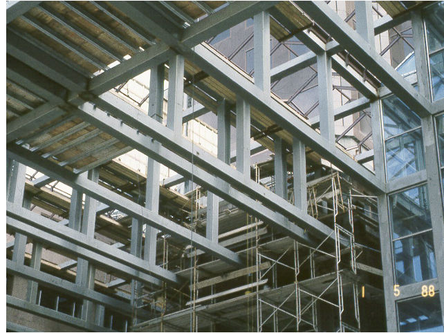
Although it is generally recommended to avoid welding in the rounded corner regions of square and rectangular HSS, it is sometimes required, such as when full-width branch-to-chord truss or frame connections are desired. Such connections are necessary, for example, in Vierendeel frames (Figure 1) where fully restrained (FR) moment connections are needed.
HSS corner welds are actually special cases of partial joint penetration (PJP) groove welds, wherein the convex surface of the chord (or through member) creates the joint preparation. In general, corner welds are used to attach flat elements that are wider than the HSS (flare-bevel), they arise in matched-width (β = 1.0) connections, and they are used to attach two HSS together at mutual corners (flare-V) such as in back-to-back, double-chord trusses.
Flare-Groove Welds
Figure 2 shows examples of flare-groove welds, where the welds are not filled flush to the edge of the HSS. The gap that can be seen at the weld root, producing a so-called “Z loss” dimension, is due to incomplete penetration and is also very typical. Table J2.2 of AISC 360 (AISC, 2016), which is reproduced as Table 1 below, gives the effective throat sizes for flare-groove welds, depending on the welding process, and presuming that the welds are filled flush with the outside face of the HSS. [Some acceptable “flush” conditions are illustrated in Figure 3-13 of AISC Design Guide 21 (Miller, 2017)]. These values are based on experimental research by Packer and Frater (2005) and they take into account the typical gap size (or Z loss) at the root, as well as typical HSS corner radii (which are often less than a 90o arc, as indicated in Figure 2). The weld effective throat sizes for flare-bevel groove welds and flare-V groove welds are expressed in terms of the HSS outside corner radius (in Table J2.2 of AISC 360-16) which, since unknown to the weld detailer, can be taken as being equal to 2t, where t is the design wall thickness. Note that AISC 360-16 Table J2.2 also appears as Table 4.1 in AWS D1.1 (AWS, 2020).

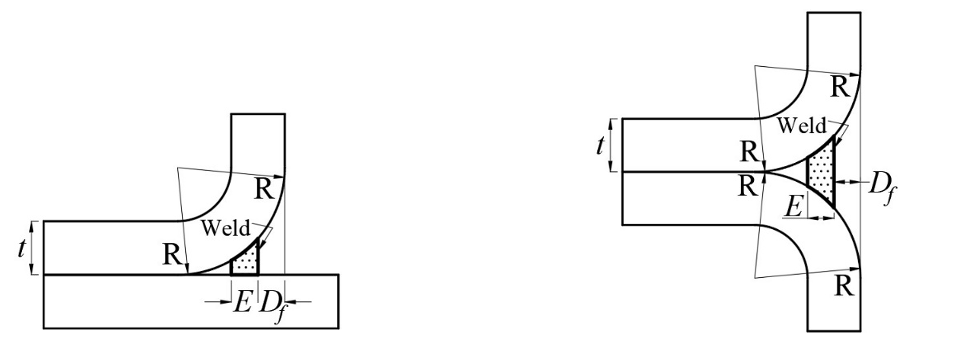
Figure 2: Examples of flare-groove welds to rectangular HSS, not filled flush to the HSS outside face

If the weld is not filled flush to the HSS face (which is the situation shown in Figure 2), these effective throat sizes in Table 1 are reduced by subtracting the “underfill” dimension, which is the distance from the weld face to the HSS face (Df), as shown diagrammatically in Figure 2(c) and (d), to obtain the effective throat, E. There is no requirement for flare groove welds to be always filled flush; if the throat of an underfilled joint is sufficient to transfer the applied loads considerable economy can be achieved by underfilling (Miller, 2017).
Table J2.2 of the AISC 360-16 does not place an upper limit on the HSS outside corner radius, hence not on the HSS wall thickness, and is conservative in the resulting effective weld sizes for large corner radii. However, AISC 360-16 does note that effective throats other than those in Table J2.2 may be used for a given welding procedure specification (WPS), if demonstrated by tests. Table J2.2 presumes that high heat input is applied (e.g., GMAW in full spray mode). Since flare-bevel and flare-V groove welds are PJP welds, for a particular effective throat size the available strength of a joint is obtained from Table J2.5 of AISC 360-16. It is possible to increase the effective weld size of a flare-bevel groove weld between an HSS corner and a flat element, even beyond that of the filled-flush situation. This can be achieved by the addition of a reinforcing fillet, which is described in Clause 4.4.2.7 and illustrated in Figure 4.6 of AWS D1.1 (AWS, 2020).
Matched-Width HSS-to-HSS Connections
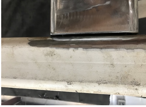
Matched-width connections between square and rectangular HSS represent another special PJP flare-groove weld situation. If the corner radius of the through (chord) member is large (due to a large wall thickness or manufacturing tolerances), there may be a considerable root gap, as illustrated in Figure 3. The root opening of pre-qualified welds is generally limited to 1/16” as detailed, or 1/8” as fitted up. Given the uncertainty about the dimensions of the HSS corner radius, some judgement and experience must be exercised with regard to handling the fabrication.
If the root gap is excessive it needs to be closed, and the AISC Manual (AISC, 2017) proposes the use of one of the solutions shown in Figure 4.
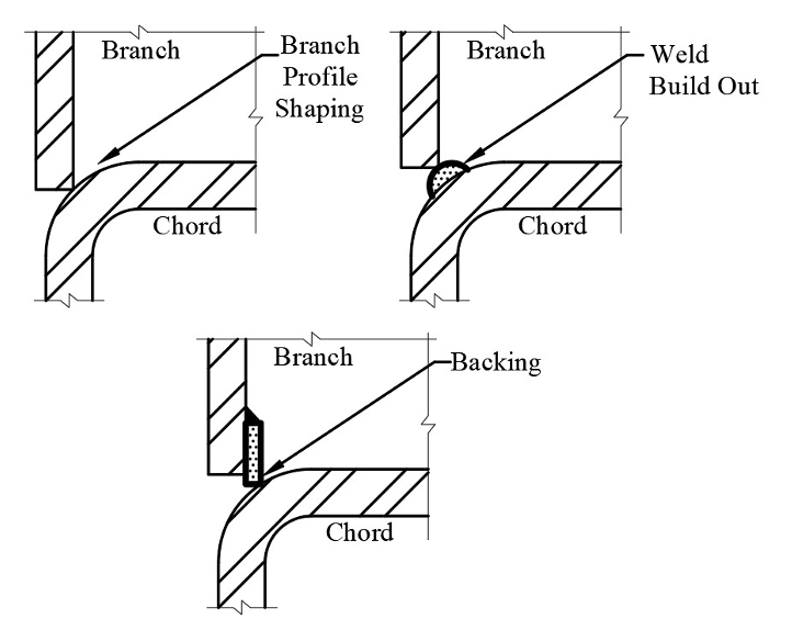
- Profile shaping of the branch, such as by machining, so that it fits the chord member contour;
- Building up the weld progressively, by “buttering”, after laying down a careful root pass;
- Using he HSS chord face, or more commonly parallel to the inside wall of the branch (as shown in Figure 4).
If the corner radius of the through (chord) member is not too large, it may be possible to straight cut the branch and weld directly in the corner region, without further weld preparation, as shown in Figure 5. No bevelling of the branch wall, which is the situation in Figure 5, then needs to be performed.
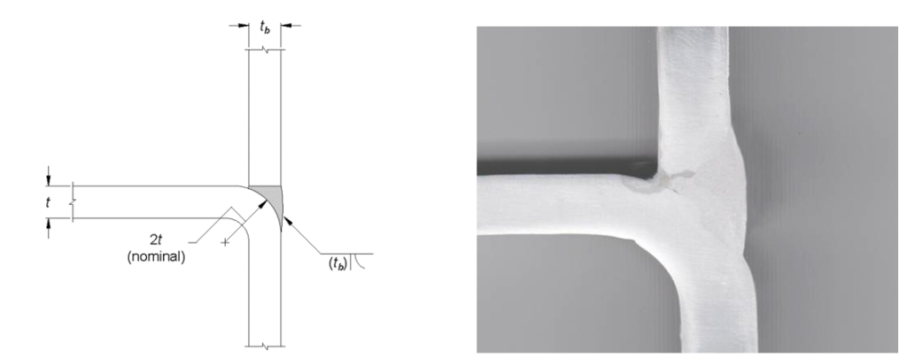
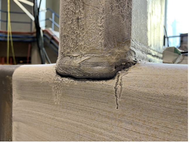
There are some instances in which matched-width HSS T-connections must be chosen, and flare-groove PJP corner welds cannot be avoided. In fully restrained (FR) moment connections the effective weld size should be specified as the branch wall thickness, tb, as shown in Figure 5. Cross sectioning of trial welds (e.g., Figure 5(b)) can always be performed to support a procedure qualification record (PQR). With proper preparation and execution, non-critical welds can be laid in HSS corners to resist very demanding load situations (see Figure 6).
Caveats
Caution is recommended when welding in zones of high cold working (such as HSS corners) in some HSS connection guidance documents, e.g. ISO 14346 Table A.1 (ISO, 2013). Minimum preheat and interpass temperature requirements for welding are covered by AWS D1.1 Clause 5.7 and Table 5.8 (AWS, 2020). For ASTM typical grades of HSS and most welding processes, the minimum temperature is 32o to 50o F, for thicknesses up to 3/4 in. Thus, the AWS requirement for pre-heating is mainly applicable to site welding conditions, but note that AWS D1.1 does not address welding in regions of high cold forming and hence may be un-conservative in that case.
References
AISC. 2016. “Specification for Structural Steel Buildings”, ANSI/AISC 360-16, American Institute of Steel Construction, Chicago, IL.
AISC. 2017. “Steel Construction Manual”, 15th. edition, American Institute of Steel Construction, Chicago, IL.
AWS. 2020. “Structural Welding Code – Steel”, ANSI/AWS D1.1/D1.1M:2020, 24th. edition, American Welding Society, Miami, FL.
ISO. 2013. “Static Design Procedure for Welded Hollow-Section Joints – Recommendations”, ISO 14346, International Organization for Standardization, Geneva, Switzerland.
Miller, D.K. 2017. “Welded Connections – A Primer for Engineers”, 2nd. edition, AISC Design Guide No. 21, American Institute of Steel Construction, Chicago, IL.
Packer, J.A. and Frater, G.S. 2005. “Recommended Effective Throat Sizes for Flare Groove Welds to HSS”, Engineering Journal, American Institute of Steel Construction, Vol. 42, No. 1, pp. 31-44.
Related Resources
- Welding of Hollow Structural Sections
- Weld Effective Lengths for Round HSS Connections
- Design of Fillet Welds to Rectangular HSS
- CJP HSS Welds: Be Informed Before You Specify
- Variety of Experience Lends Itself to Mentorship: A Conversation With Duane Miller
- Webinar On Demand: Know Your HSS Welds
- Webinars On Demand: HSS Weld Seams
HSS Resources
Access valuable HSS tools and resources, including live webinars, producer capability tool, spreadsheet design aids, manuals, articles and more.