CJP HSS Welds: Be Informed Before You Specify
By Kim Olson, PE
Technical Consultant, Steel Tube Institute
Weld design is not exempt from the numerous differences between wide-flange (WF) and hollow structural section (HSS) connection design. Unlike open sections where welding is possible on both sides of the flanges and web, the interior of HSS sections commonly used in building structures cannot be accessed.
Complete joint penetration (CJP) welds are unquestionably the least preferred weld type from a fabrication and cost point of view. Unfortunately, they tend to be a frequently specified weld for HSS construction. This is due to several factors including ease and speed of weld capacity calculation and lack of knowledge or understanding of HSS weld design. It is generally felt that CJP welds are better than partial joint penetration (PJP) groove welds for a variety of reasons. However, only in fatigue-loading conditions is this actually true.
Specifying a CJP weld should be a designer’s last option and is rarely required. AISC 360-16 Table J2.5 identifies the strength of a CJP groove weld to be equal to the available strength of the base metal, assuming matching filler metal is used to perform the weld. In this case, the result is a weld that develops the full yield strength of an HSS member. For most designs, like in a truss branch member, the member’s utilization rate is low. Developing the strength of the member is pointless and uneconomical. It is better practice to design the weld for the actual applied forces. Additionally, limit states other than the weld design will likely govern an HSS connection design, resulting in the lack of need for full yield strength capacity in the weld. Too often the designer takes the easy way out. Specifying a CJP weld is overkill.

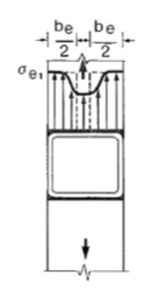
If connecting a plate (or beam flange) transverse to an HSS, or an HSS branch to a rectangular HSS member, AISC 360-16, Section K1.2a requires a reduced width (“effective width”) be used when calculating the local yielding of the connected plate or branch member. This is because the transverse plate or HSS is not uniformly loaded across its width (Figure 1). Due to the relatively high stiffness of the HSS wall adjacent to the sidewalls, the stress in the plate or branch member is highest at the outer portions of the section and lowest in the middle. Due to this effective width, it is rarely possible to achieve a connection capacity equal to the full yield strength of the member being connected to an HSS and, therefore, often eliminates the need for a full capacity weld.
Generally, for steel construction, if CJP welds are required, it is preferred and most economical to use steel backing. However, backing is sometimes detrimental to the connection design. In cyclically loaded structures, structures subjected to fatigue or some members in a seismic force resisting system, backing cannot be left in place. Investigations of events, such as the Northridge earthquake, show backing left in place creates stress risers which contribute to cracking and connection failures. Not all members in a seismic force resisting system require backing to be removed, and these are clearly identified in the AISC 341 Seismic Provisions.
In the cases where a CJP weld must be made from one side without backing, which is common with HSS, the open root dimensions must be precisely controlled and the minimum groove angles assured. The first step in creating this weld is a backup weld at the root. Careful preparation of the joint is required to ensure the proper fit-up to allow the placement of this backup weld. Because of the limited access and extreme skill required to perform this weld, AWS D1.1 requires a 6GR welder certification for an unbacked CJP weld. This welder certification is very difficult to achieve and is relatively uncommon in many areas of the country. It is required for unbacked CJP welds on tubular members for T-, Y- and K-connections for all welding positions. As a result, the labor component of the weld cost is extremely high.
With appropriate backing, the difficulties of the open root welding go away. With backing, the welder requirements drop down to 3G and 4G requirements, and a greater variation in fit-up can be tolerated without adversely affecting the welding quality. This is also the case for HSS to base plate welds.
There are many methods that fabricators have used to fit backer bars inside an HSS. Accurate fitting of backing bars is important. Rectangular sections have the ability to accept backer bars easily. Backing can be more difficult to provide for round HSS as it must account for any ovality in the member that falls within the production standard’s tolerances. Additionally, backing for a round HSS to round HSS connection is virtually impossible to achieve. Commonly, bar stock is formed to create a backing ring. Some fabricators cut backing from a thick plate by tracing the inside surface of the HSS and then cutting the plate to match. The plate can then be left solid or hollowed out for ease of handling and decreased weight.

These backer bars must be left in place as it is impossible to remove them. This is typically acceptable for statically loaded structures. Backing is required to be continuous in most applications per AWS D1.1; however, Clause 7.9 allows exceptions for HSS, provided several conditions are met. AISC Design Guide 21 provides a detailed explanation for the allowable discontinuity of backer bars for HSS.
Ultrasonic testing (UT) can be successfully used to inspect these types of welds. However, the results depend highly on the experience of the UT technician and may lead to conflict among all parties involved. More inspection effort should be placed on the inspection prior to and during the welding process. This includes verifications of the fit-up to ensure proper root openings and angles and visual inspection during the welding process.
Specifying a CJP should be done only if essential to the design and all other weld types have been explored. And when done, it is beneficial to consult a fabricator in order to detail the joint as effectively as possible to reduce costs and any fabrication issues.
Resources
AISC. 1997. “Hollow Structural Sections Connections Manual,” American Institute of Steel Construction, Chicago, IL.
AISC. 2016. “Specification for Structural Steel Buildings,” ANSI/AISC 360-16, American Institute of Steel Construction, Chicago, IL.
AWS. 2020. “Structural Welding Code – Steel,” AWS D1.1/D1.1M:2020, American Welding Society, Miami, FL.
Packer, J.A., Sherman, D. and Lecce, M. 2010. “Hollow Structural Section Connections,” Steel Design Guide 24, 1st edition, American Institute of Steel Construction, Chicago, IL.
Post, J.W. 2003. “Box-Tube Connections; Choices of Joint Details and Their Influence on Costs,” Proceedings of National Steel Construction Conference.
Miller, D.K. 2017.”Welded Connections – A Primer for Engineers,” Steel Design Guide 21, 2nd edition, American Institute of Steel Construction, Chicago, IL.
May 2020