New Concepts for Bolted HSS Column Splices
By Jeffrey A. Packer
Bahen/Tanenbaum Professor of Civil Engineering, University of Toronto, Ontario, Canada
Reviews of HSS general splicing techniques are already available (Packer, 2016, 2018; Manor, 2018), but the quest for HSS-to-HSS site-bolted column splice solutions continues. Expansion bolts with one-side access, for bolting through the walls of HSS, are well known, such as the Hollo-Bolt by Lindapter (2022). Although these connectors have been featured on some major structures (e.g. Kimmel Center roof in Philadelphia), their load capacity is limited by a 5:1 factor of safety and the fact that over-size holes in the HSS are required to accommodate the expansion bolt collar. Thus, expansion-bolt connectors are generally more appropriate for fixing services, flooring, glazing and cladding. Other proprietary “blind bolts” are also on the market (Manor, 2021), but careful attention needs to be paid to their certifications, equivalency to regular high-strength ASTM structural bolts, their ability to be pretensioned, and availability. Now, two new and innovative concepts for HSS column splicing have recently been demonstrated, both of which utilize ASTM F3125 Gr. A325 or Gr. A490 bolts (ASTM, 2019a), and each addresses the problem of holding nuts (or equivalent) in place on the inside of the HSS by novel methods.
Shuriken, by Atlas Tube
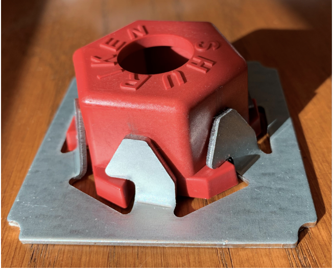
The Shuriken, named after a Japanese throwing star or Ninja star weapon, is a device that holds one nut in place, inside a square or rectangular HSS member. A polymer cap that fits over the nut prevents it from rotating, and steel tabs prevent rotation of the polymer cap, while allowing it to move laterally for adjustability (see Figure 1).
A set of Shurikens are located in their correct positions by tack welding them to a steel “splice plate” in the shop, at the 4 Shuriken corners which are notched in Figure 1. The splice plate itself will have drilled, punched, or cut bolt holes (as will the HSS wall) for passage of the bolt. Four splice plates – one for each HSS wall – are then inserted and bolted into one of the coaxial HSS members, which can be done in the shop, ready to receive the other HSS member. The weld seam on the interior of both HSS members needs to be ground flat in locations where a splice plate contacts the seam. It is recommended that all bolts be initially only snug-tight (or less, to aid with site fit-up), then tightened fully or pretensioned (if required) after full field assembly. A set of Shurikens installed within the inside of an HSS, welded onto four steel retaining plates, is shown in Figure 2(a).
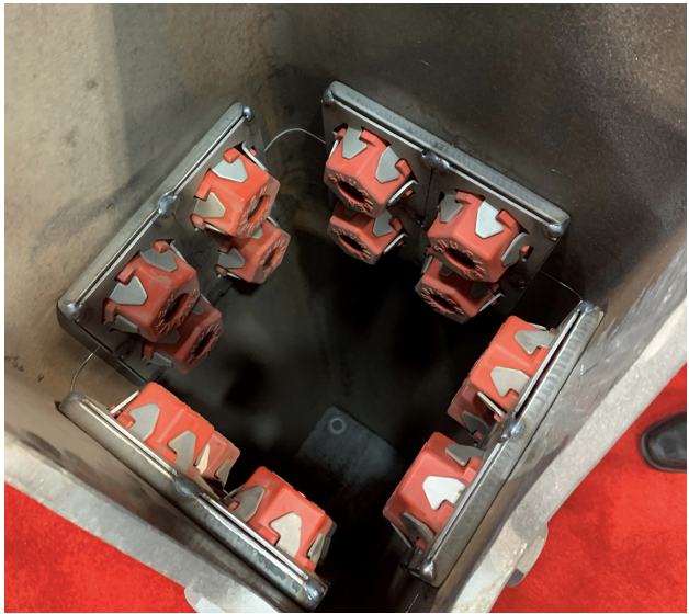
Figure 2(b) illustrates the clean external appearance of a column splice that joins two identical HSS members. If one wanted to reduce the wall thickness of the upper HSS column, a second shim plate could be used beneath each splice plate within the HSS, and the entire double-plate assembly could be shop-bolted into place inside the upper (thinner) HSS column prior to site bolting to the lower column. As shown in Figure 2, the bolts are loaded in single shear, will likely have to be fully threaded, and the bolts – with threads intercepted – may govern the connection strength. To increase the bolt shear capacity, an external cover plate could be added to the connection (as shown in Figure 3) which places the bolts in double shear. If F959 direct tension indicators (ASTM, 2017) are used for pretensioning, as recommended by Atlas Tube for all pretensioned bolts, an F436 washer will also be required under the bolt head as well (RCSC, 2020), which will affect the bolt length. As Figure 2(a) suggests, the bolts should not be longer than necessary to avoid fouling bolts from the neighboring face.
Shuriken nut holders are available, at present, for 3/4 in. and 7/8 in. diameter bolts, but Shurikens for 1 in. and 1-1/8 in. bolt diameters are under development. The Shurikens are inexpensive, can be purchased online, and come in boxes of 16. A limitation of the product is the footprint of the steel base (see Figure 1), which has a width of approximately 3.0 in. According to Part 1 of the Manual (AISC, 2017), the “workable flat” width of a square HSS can be taken as the HSS total width, B, less two outside corner radii of 2.25tnom, so this means that only a single bolt per row per column face can be used for a HSS 6” x 6” member. In order to fit two Shurikens side-by-side on an internal column wall (per Figure 2), one needs a HSS 8” x 8” x 3/8” or thinner-walled member.
Design of the connection itself entails application of traditional limit states for bolted joints, which are given in Chapters D and J of the Specification (AISC, 2022). These limit states are common to the Cast Steel Insert connection, discussed below.
Cast Steel Insert, by Bull Moose Tube
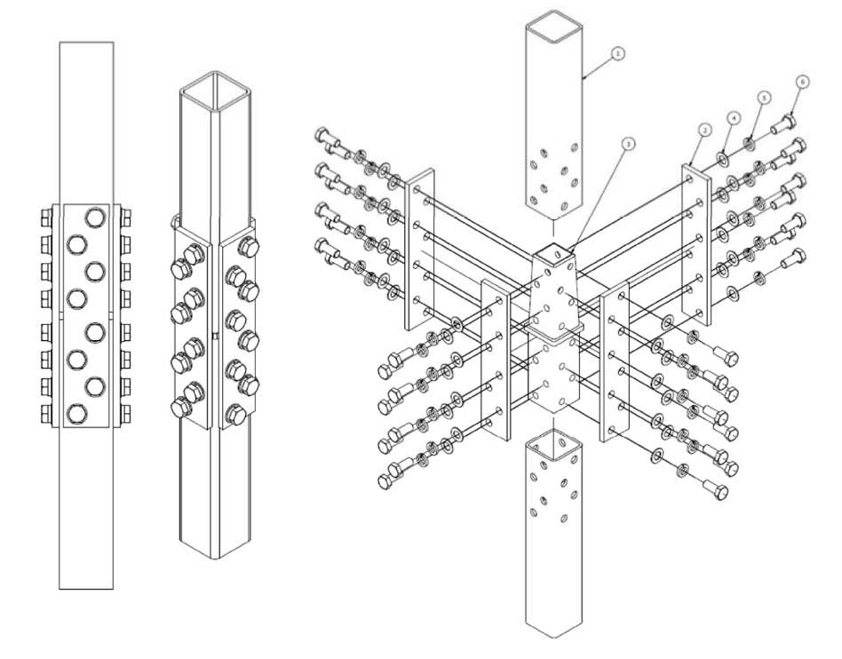
The Shuriken splice requires the fabricator to make internal splice plates to suit the connection design, to weld the Shuriken nut holders to these plates, perform some shop fitting, and to assemble the connection in the field by mating the second HSS over four protruding splice plates. An alternative is to use one pre-engineered cast steel connection piece which – on site – is placed in the lower HSS column and then the upper HSS column is lowered over the tapered nose of the casting. The connection is completed by bolting through the HSS into tapped holes in the casting, which serve as the “nuts”. This concept is illustrated in Figure 3, with external cover plates on the four HSS faces. The casting is made of a high-strength steel to A148 Gr. 135-125 (ASTM, 2020a) which is of “nut quality”, and is hollow throughout its length. The casting bolt holes are threaded through the full thickness, which is comparable to a heavy hex nut, so that the required number of threads is provided for full pretensioning of the bolts. This nut substitution complies with the “Bolt Council Specification” Clause 2.12.1(1) for alternative-design bolting components and assemblies (RCSC, 2020).
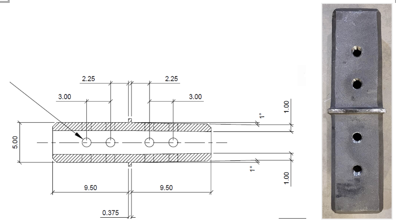
At mid-length the casting has a ledge, which protrudes out to just beyond the wall thickness, with this ledge locating the casting in the correct position to align with the bolt holes in the HSS walls. The upper half of the casting has a slight taper to be erection-friendly, as shown in the section view of Figure 4. Also, the four corners of the casting are beveled to accommodate the rounded corners of the cold-formed HSS member. Ultimately, cast steel inserts are to be designed for off-the-shelf, pre-engineered connections to a range of popular HSS column sizes (6” x 6”, 8” x 8”, 10” x 10”, 12” x 12”, etc.)
To validate this HSS splicing method, “proof-of-concept” laboratory testing was performed on several full-scale test specimens, under both axial tension and compression loading. For each connection, two HSS 6” x 6” x 3/8” A1085 (ASTM, 2015) were joined with one cast steel insert, four Gr. 50 steel cover plates measuring 4” x 3/4″ and 16 ASTM F3125 Gr. A490 bolts (ASTM, 2019a), as shown in Figure 5.
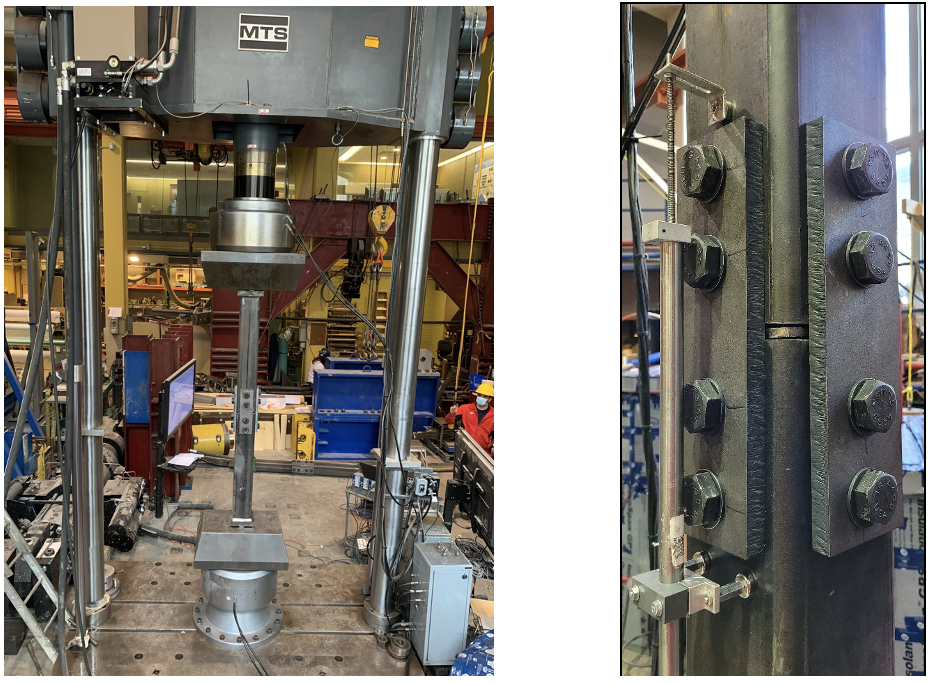
Besides tension/compression loading, experimental variables involved snugging versus pretensioning the bolts, and varying the hole locations in the HSS members. The potential failure modes for the cast steel insert connection (with external cover plates), when loaded in tension, are listed below. Also shown is the calculated capacity for each limit state according to Chapters D and J of AISC 360-22 (AISC, 2022) and RCSC (2020), for the actual test specimens, without resistance factors and using measured mechanical and geometric properties.
- Bolt shear: 890 kips (A490 bolts in double shear)
- HSS gross area yielding: 465 kips
- HSS net section rupture: 451 kips
- HSS bolt tear-out: 525 kips (for most-critical bolt-hole layout)
- HSS bolt bearing: 582 kips
- Cover plate gross area yielding: 602 kips
- Cover plate net section rupture: 653 kips
- Cover plate bolt tear-out: 957 kips
- Cover plate bolt bearing: 1248 kips
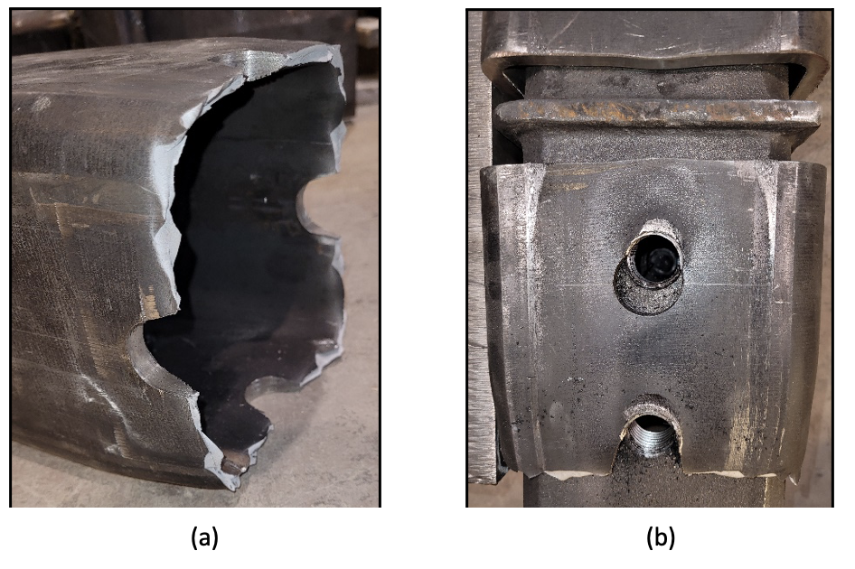
As can be seen, the governing limit state is HSS net section rupture, which duly occurred in the tension connection tests (see Figure 6). Although many limit states involving the cover plates and bolts can be made non-critical, drilling bolt holes in the HSS – even just four at a cross section – significantly reduces the net area and induces net section rupture. It should be noted that these limit states are also the same for the Shuriken connection. Thus, both of these connection types – while suitable for most HSS splice situations – will not be applicable to high-demand, seismic force-resisting column splices where significant connection over-strength is required (in excess of AgFy or ZFy). In compression, a capacity in excess of the HSS squash load was achieved and the test specimens failed by a combination of overall buckling and inelastic local buckling of the cross section. Of note is that the cast steel inserts (and threads) never received any distress in any test and were potentially re-usable. Material tests on the cast steel also confirmed its excellent ductility, including Charpy V-notch absorbed energy of over 70 ft-lbs at –40oF. The amount of bolt tensioning does not influence the above-listed limit states.
References
AISC. 2022. “Specification for Structural Steel Buildings”, ANSI/AISC 360-22, American Institute of Steel Construction, Chicago, IL.
AISC. 2017. “Steel Construction Manual”, 15th edition, American Institute of Steel Construction, Chicago, IL.
ASTM. 2015. “Standard Specification for Cold-Formed Welded Carbon Steel Hollow Structural Sections (HSS)”, ASTM A1085/A1085M-15. American Society for Testing and Materials International, West Conshohocken, PA.
ASTM. 2017. “Standard Specification for Compressible-Washer-Type Direct Tension Indicators for Use with Structural Fasteners, Inch and Metric Series”, ASTM F959/F959M-17a, American Society for Testing and Materials International, West Conshohocken, PA.
ASTM. 2019a. “Standard Specification for High Strength Bolts and Assemblies, Steel and Alloy Steel, Heat Treated, Inch Dimensions 120 ksi and 150 ksi Minimum Tensile Strength, and Metric Dimensions 830 MPa and 1040 MPa Minimum Tensile Strength”, ASTM F3125/F3125M-19e2, American Society for Testing and Materials International, West Conshohocken, PA.
ASTM. 2019b. “Standard Specification for Hardened Steel Washers Inch and Metric Dimensions”, ASTM F436/F436M-19, American Society for Testing and Materials International, West Conshohocken, PA.
ASTM. 2020a. “Standard Specification for Steel Castings, High Strength, for Structural Purposes”, ASTM A148/A148M-20e1, American Society for Testing and Materials International, West Conshohocken, PA.
Lindapter. 2022. https://www.lindapter.com/us/product-category/hollo-bolt
Manor, M. 2018. “HSS Column Splices”, Steel Tube Institute Technical Article.
Manor, M. 2021. “HSS Blind Structural Fasteners”, Steel Tube Institute Technical Article.
Packer, J.A. 2016. “HSS Splices”, Steel Tube Institute Technical Article.
Packer, J.A. 2018. “Hidden Bolted HSS Splices”, Steel Tube Institute Technical Article.
RCSC. 2020. “Specification for Structural Joints using High-Strength Bolts”, Research Council on Structural Connections, Chicago, IL.
October 2022
Meeting in the Middle: Understanding the Sales and Engineering Sides of Bolted HSS Column Splices
STI interviewed Brad Fletcher, senior sales engineer at Atlas Tube, to find out more behind the Shuriken nut keeper.
All About the New Cast Steel Insert From Bull Moose Tube
We spoke with Mark Abernathy, manager of field applications at Bull Moose Tube, about how the new cast steel insert should be used…
Related Article
Read an Expert Reactions to the Directionality Increase for Fillet Welds to HSS in our peer perspective article.