HSS Beam to HSS Column Connections
By Cathleen Jacinto, PE and SE, and Brady Golinski, PE
Technical Consultants, Steel Tube Institute
July, 2023
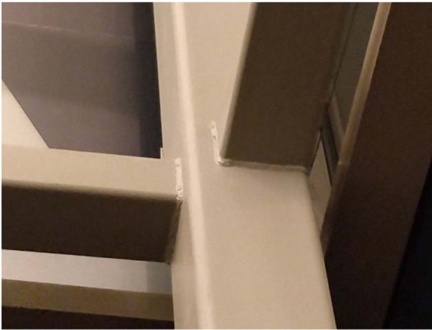
Hollow Structural Section (HSS) beams have become a popular choice as girt members in modern construction, playing a crucial role in supporting vertical gravity floor loads and addressing out-of-plane wind and seismic forces. Their versatility extends further as they also provide support for architecturally-driven features such as exposed canopies or roofs, often incorporating cantilevers. Additional applications for HSS beam to HSS column connections include, but are not limited to, HSS truss chord to HSS column connections and prefabricated modular construction. As the demand for HSS beams continues to grow across diverse industries, this article serves as a resource offering a broad library of detailing options for connecting HSS beams to HSS columns under varying loading conditions. Furthermore, it shall explore required limit state checks to consider through an illustrative example.
Simple Shear Connection Details
HSS Beam Transferring Vertical Shear Only
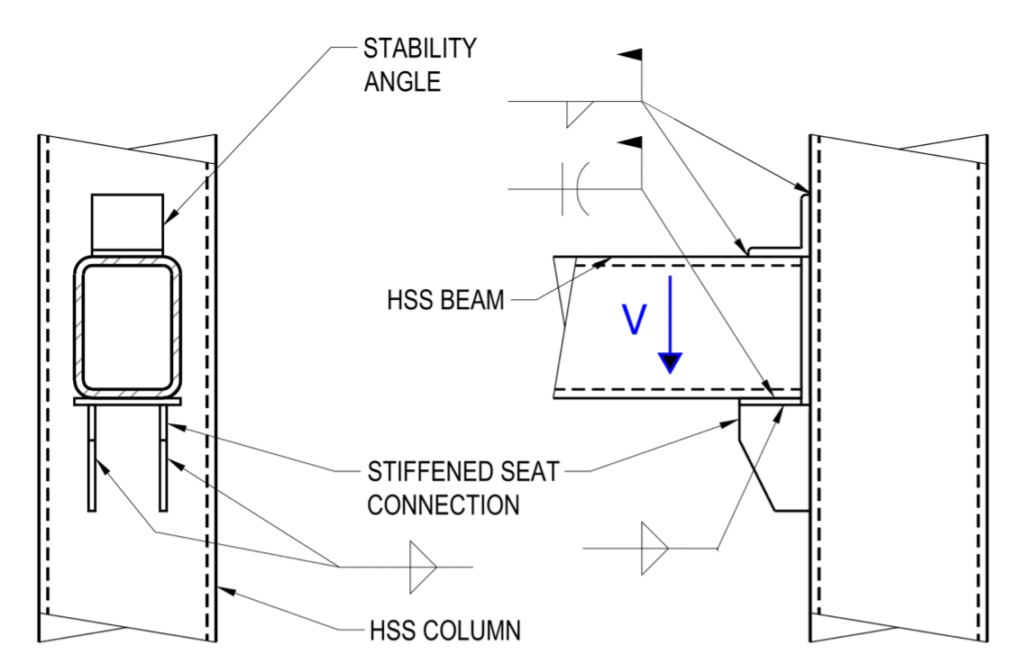
Refer to Figures 2 through 10 for simple shear connection details for HSS beam to HSS column connections. These details are intended to resist vertical shear only. However, note that a few details (i.e. Figures 3 and 5) bear the potential to transfer horizontal shear as well, depending on the magnitude of the horizontal shear load and connection geometry.
Figure 2 shows an HSS beam to HSS column stiffened seat connection, for which the HSS beam transfers vertical shear only. The horizontal seat plate need not be welded to the HSS column, only the vertical stiffener plates below the seat plate shall transfer vertical shear to the column.
HSS Beam Transferring Vertical and Horizontal Shear
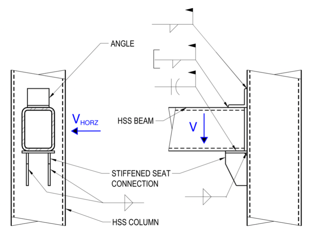
If the HSS beam transfers both vertical shear and lateral horizontal shear, the horizontal seat plate can be welded directly to the HSS column to transfer horizontal shear as shown in Figure 3. In Figure 3, the top angle is also designed to share in resisting horizontal shear along with the horizontal seat plate. This is demonstrated further in the example provided at the end of this article. In both versions of this detail, the stiffened seat connection plate and vertical stiffeners are shop welded to the HSS column. The HSS beam and top angle are field welded.
In this stiffened seat connection transferring vertical shear, the shear load travels from the HSS beam through the horizontal seat plate to the vertical stiffeners below. Note that the bottom wall of the HSS beam must be checked for this vertical reaction, V. In this case, the HSS beam is considered to be the chord of the connection, and the top of the vertical stiffener plate acts as a longitudinal plate branch member. Refer to the Longitudinal Plate Connections in the STI Limit State Axial Table, for corresponding limit states to check. After checking the HSS beam at the seat connection, the next step is to check the transfer of the vertical shear force from the vertical stiffener plates to the HSS column. This is a more typical connection, akin to a single plate connection design. In this case, the chord is the HSS column and the branch is the vertical stiffener plate. The Longitudinal Plate Connections in the STI Limit State Axial Table can again be utilized to perform the connection checks. The example at the end of this article demonstrates how to perform these limit state checks for the vertical shear transfer as well as the horizontal shear transfer.
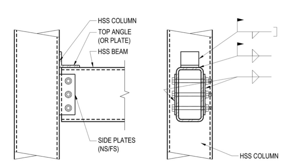
Figure 4 shows a simple shear HSS beam connection utilizing through-bolts at two shear plates and a top stability angle. Through-bolts shall only be used in a snug-tight condition and can be pretensioned only if the HSS is reinforced. Additional discussion on through-bolting HSS is discussed in STI article “Connecting Hollow Structural Members with Through-Bolts.”
Figures 5 through 10 illustrate various options for HSS beam to HSS column simple shear connections primarily transferring vertical shear.
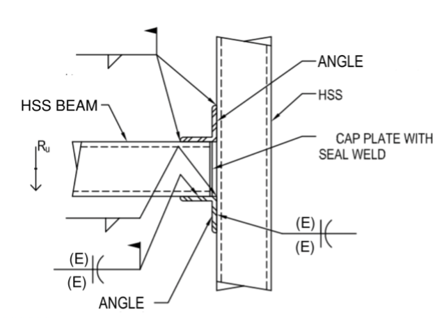
Figure 5 represents an unstiffened seated connection with a top stability angle. For a connection with a high vertical shear, a stiffened seated connection can be provided per Figure 2. Flare-bevel PJP groove welds are shown at the bottom angle to HSS column, assuming the angle width is closely matched to the HSS column width. However, the angle width can bear on the workable flat of the HSS column and in that case, fillet welds can be provided in lieu of PJP welds.
Figure 6 shows a narrow HSS beam framing into a wide HSS column. This connection geometry allows for double angles to be placed on both sides of the narrow HSS beam welded to the HSS column. The eccentricity between the angle welds and bolted connection may limit the connection capacity, and should be used for lightly-loaded beams. The angles-to-HSS beam connection consists of standard high-strength bolts and the use of an access hole to allow a contractor to tighten the bolts inside the HSS with a wrench. The access hole needs to be carefully coordinated between the engineer and steel contractor. Loss of area and connection capacity shall be considered in the design of this connection, and the access hole can be required to be closed and sealed after bolt installation.
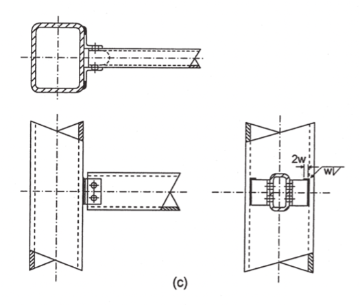
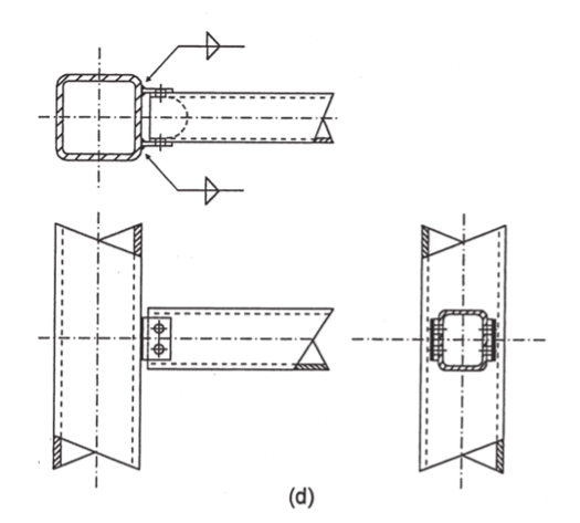
Figure 7 allows for an HSS beam more closely matched in width to the HSS column, utilizing double shear plates. This double plate connection offers relatively greater stiffness than the double angle connection per Figure 6. The detail shows the use of standard bolts assuming an access hole will be provided, but a through-bolt connection can also be utilized in lieu of standard bolts. Figure 8 is a variation of this connection where the width of the members are equally matched. It may be necessary to spread pairs of plates slightly with jacks after the welds cool because welding contraction will tend to deflect and pull the plates together.
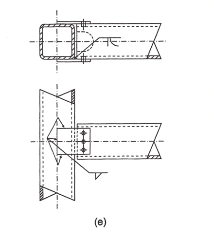
Figure 9 illustrates two field-bolted WT connecting elements to transfer vertical shear at the HSS beam to HSS column joint. The vertical legs of the WT should be welded to the HSS column and include a short return weld at the top corners to allow for rotation in this simple shear connection. Figure 10 is a variation of this connection utilizing double angles welded to the HSS column in lieu of a WT. This allows for double shear in the bolts to achieve greater bolt capacity.
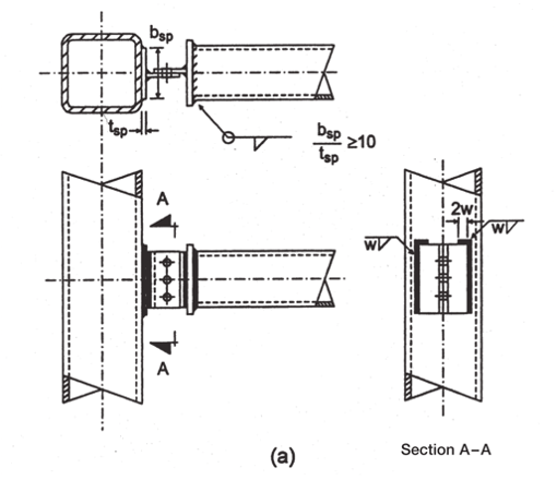
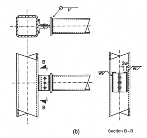
CIDECT DG9, Fig. 5.12(b)
Key Design Consideration: Fixity
In simple shear connections, HSS beams typically utilize two vertical sidewalls that act as webs to transfer vertical shear. Since HSS beams are optimal in resisting torsional loading, it is common for HSS beam connections to be subjected to torsional loading, axial and sometimes moment forces. Typically, HSS beams with combined shear, axial or torsion will require end plate connections or connections with double or quadruple plates or angles at all four HSS walls. When detailing the HSS beam connection, it is critical for the connection engineer to be cognizant that connecting the top or bottom walls of the HSS beam to its support could change the fixity of the connection and restrain the beam end from rotating. If the intent is to provide a simple shear connection with no rotational restraint nor fixity at the end, any additional fixity resulting from restraint at the top and bottom walls of the HSS should be accounted for in the HSS member design.
Torsional Connection Details
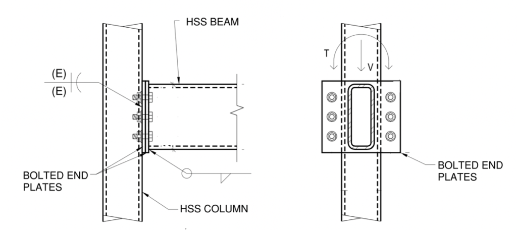
To transfer shear (vertical and/or horizontal) and torsional loading at the end of the HSS beam, a bolted end plate connection as shown in Figure 11 is a common option. In this detail, bolts are located at the sidewalls of the HSS beam to increase the torsional moment arm for a more efficient connection. STI Manual Volume 3 includes Example 3-5.10 to demonstrate the design of this end plate connection under shear and torsional loading.
Another option to transfer vertical shear, horizontal shear or torsion is a variation of the through-bolt connection and is shown in Figure 12. Top and bottom plates are added to allow for transfer of horizontal shear loads or torsion to the HSS columns. However, this connection is no longer a simple shear connection, and there is rotational restraint due to the top and bottom plates. This needs to be considered in the HSS beam and column member design.
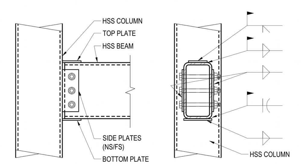
The four-plate connection shown in Figure 12 can also be utilized to resist moment or axial loading. However, it must be noted that due to the flexibility of the HSS column face receiving the connection, we cannot achieve a fully rigid connection. The moment connection is more of a partially restrained moment connection that has the potential to see some rotation depending on the thickness of the HSS wall. For best results, choose an HSS column with a thick wall to best transfer moment or axial forces through the connection. To achieve a fully rigid connection, internal plates welded to the interior of the HSS column can be provided.
Offset Girt Detail Options
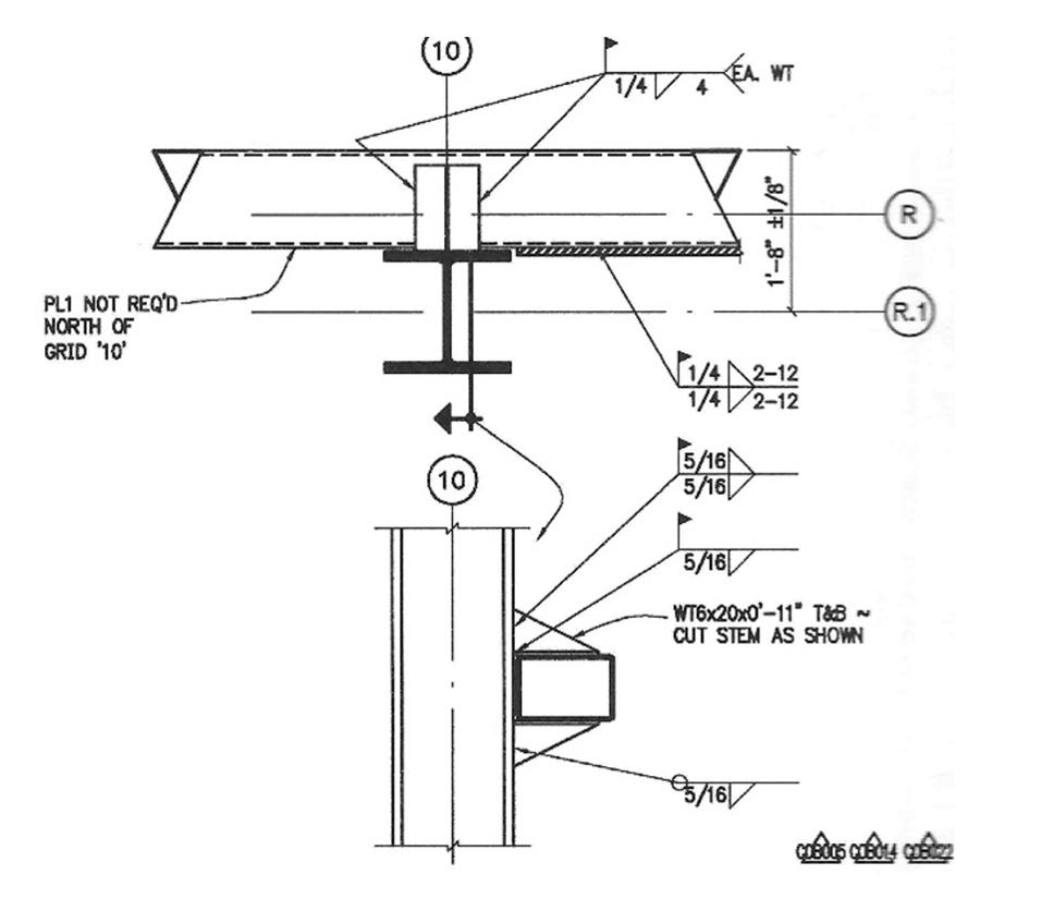
HSS girt to HSS column connections that support exterior wall facades often require the exterior face of the HSS girt to be flush to the exterior face of the HSS column. For additional considerations in this type of connection, refer to the STI article “Laterally Offset HSS Connections.”
Where the HSS girt width is located completely offset from the building column width, Figure 13 shows a connection detail utilizing a seated connection that can transfer both vertical and horizontal shear.
HSS Knee Connections
Where two HSS beams meet at a corner of a framing plan, there are several options to detailing this HSS knee connection. Design considerations and details for rectangular and round HSS knee connections are further described in STI article “HSS Knee Connections.”
HSS Girt to HSS Column Example
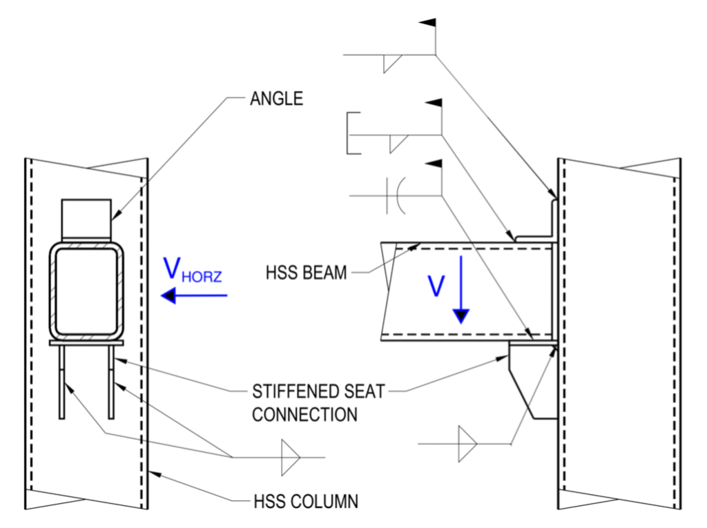
HSS beams work well at the perimeter of a building when there are both vertical gravity floor loads to support as well as horizontal wind/seismic loads that need to transfer from the exterior wall system through the girt to the exterior column. Due to the doubly symmetric closed shape, HSS are able to support and transfer these loads in different directions simultaneously. Below is a connection example demonstrating both the detailing and limit states necessary to ensure proper transfer of these loads to meet the requirements of simple shear connections.
Beam/Girt = HSS8x6x3/8 A500C (strong axis vert)
Column = HSS8x8x3/8 A500C
Seat plate = 1/2x7x0’-5, 50 ksi
Stiffener plates = 1/2×10, 50 ksi (2 plates)
Top angle = L4x4x1/4×0’-4
beam bearing length = 4”
Loads:
Vertical Ru = 80 k
Horizontal Ru = 30 k
Consider the girt to be pinned in both directions
At the time this example was developed, the AISC 360-22 Specification and 15th Edition Manual are the latest AISC steel standards and are the basis for this example.
There are actually two connections that need to be considered in this detail. The first connection is between the girt and seat plate stiffeners. The reaction of the stiffeners is akin to a longitudinal plate to HSS connection in compression. The second connection is between the seat plate stiffeners and the HSS column, which is a longitudinal plate T-connection with shear load.
Vertical Shear Connection
1. Bearing in HSS girt walls
The configuration of this connection most closely matches a T-connection where the vertical stiffener plates are longitudinal plates that act as the walls of the branch imparting a reaction load on the girt that serves as the chord of this connection. The force is located at the end of the girt.
a. Local web yielding
k = 1.5tb = 1.5 × 0.349 in = 0.524 in
Rn = 2Fyw tw (2.5k + lb ) [AISC 360-22 Equation J10-3]
ϕRn = 1.0 × 2 walls × 50 ksi × 0.349 ×(2.5 × 0.524 in + 4 in) = 185 k
185 k > 80 k OK
b. Local web crippling
Since this girt is not transferring any moment or axial load, U = 0, Qf = 1.0
lb = 4 in d = H – 3t = 8 in – 3 × 0.349 in = 6.95 in
lb ⁄ d = (4 in) ⁄ (6.95 in) = 0.575 > 0.2

273 k > 80 k OK
2. Induced moment in stiffeners
The stiffener plates are assumed to carry the beam reaction at a distance of 0.8W from the column face as discussed. [AISC 15th Edition Manual Page 10-94]
Eccentricity = 0.8W = 0.8 × 4 in = 3.2 in
Sx = (tstdst2) ⁄ 6 = (0.5 in × (10 in)2 ⁄ 6 = 8.33 in3 per plate
Mu = 80 k × 3.2 in = 256 k – in
ϕMn = ϕFypSx = 0.9 × 50 ksi × 8.33 in3 = 375 k – in
375 k – in > 256 k – in OK
3. Shear in stiffeners
a. Shear yielding
Rn = 0.6Fyst Agv [AISC 360-22 Equation J4-3]
Agv = 0.5 in × 10 in × 2 plates = 10 in2
ϕRn = 1.0 × 0.6 × 50 ksi × 10 in2 = 300 k
300 k > 80 k OK
b. Shear rupture
Rn = 0.6Fust Anv [AISC 360-22 Equation J4-4]
Anv = Agv = 10 in2
ϕRn = 0.75 × 0.60 × 65 ksi × 10 in2 = 293 k
293 k > 80 k OK
4. Combined loading on stiffeners

5. Punching shear of the HSS column face at the stiffeners

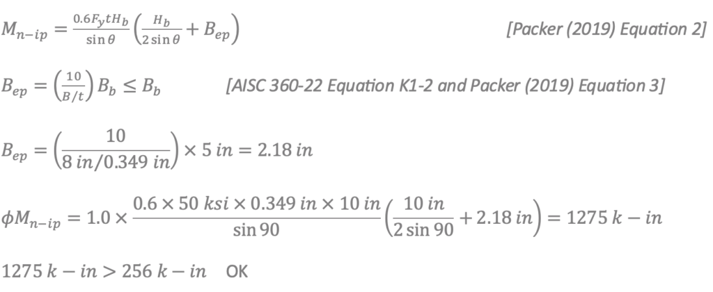
6. Plastification of the HSS column face

Assume column forces at the connection are Pu = 250 k (compression) and Mu = 0.
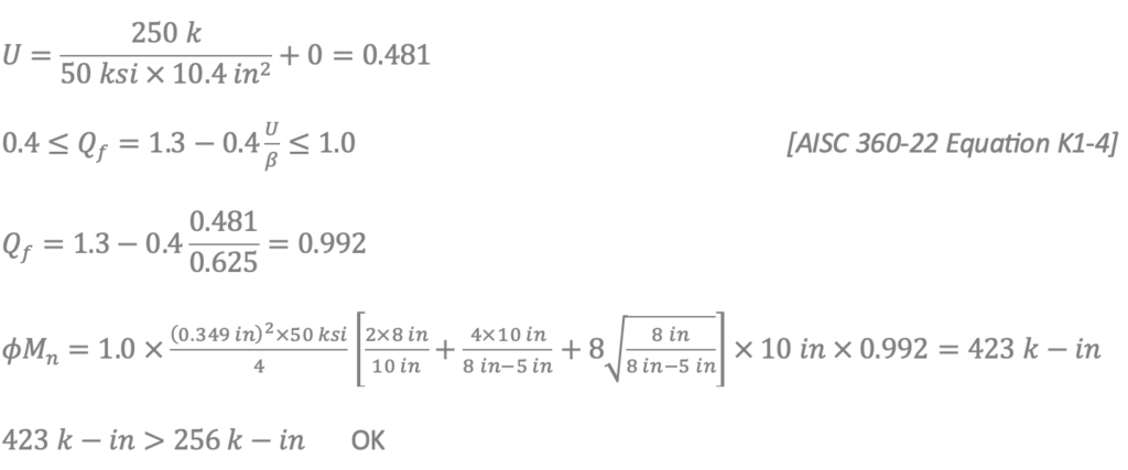
7. Shear yielding (punching) of the HSS column face due to vertical stiffener plates
When the HSS column member is being designed, the column member should be designed for the eccentricity of the vertical shear load and the centroid of the seated connection, or Mu = 256 k-in as calculated above.
8. Local yielding of column sidewalls
The beam connects at a distance greater than H from the end of the column. Therefore, end distance considerations per AISC 360-22, Section K1.4 are not required.
Rn = Fywtw (5k + lb ) [AISC 360-22 Equation J10-2]
tw = k = tcol
Moment arm = 0.5(Hb + 5k) = 5.87 in
ϕRn = 1.0 × 50 ksi × 0.349 in × (5 × 0.349 in + 10 in) = 205 k
ϕMn = 205 k × 5.87 in = 1203 k – in
1203 k – in > 256 k – in OK
Horizontal Shear Connection
Design the horizontal seat plate to transfer horizontal shear from the HSS beam to the HSS column. The design and detailing of the horizontal shear connection must not inhibit the rotation required by the vertical shear connection (see AISC 360-22 Section J1.2 and AISC 15th Edition Manual page 9-14.)
9. Horizontal Shear in seat plate
a. Shear yield
Rn = 0.6FyAgv [AISC 360-22 Equation J4-3]
Agv = 0.5 in × 7 in = 3.5 in2
ϕRn = 1.0 × 0.6 × 50 ksi × 3.5 in2 = 105 k
105 k > (30 k) ⁄ 2 = 15 k OK
b. Shear rupture
Rn = 0.6FuAnv [AISC 360-22 Equation J4-4]
Anv = Agv = 3.5 in2
ϕRn = 0.75 × 0.6 × 65 ksi × 3.5 in2 = 97.7 k
97.7 k > (30 k) ⁄ 2 = 15 k OK
10. Horizontal Shear in top angle
a. Shear yield
Rn = 0.6FyAgv [AISC 360-22 Equation J4-3]
Agv = 0.25 in × 4 in = 1.0 in2
ϕRn = 1.0 × 0.6 × 36 ksi × 1.0 in2 = 21.6 k
21.6 k > (30 k) ⁄ 2 = 15 k OK
b. Shear rupture
Rn = 0.6FuAnv [AISC 360-22 Equation J4-4]
Anv = Agv = 1.0 in2
ϕRn = 0.75 × 0.6 × 58 ksi × 1.0 in2 = 26.1 k
26.1 k > (30 k) ⁄ 2 = 15 k OK
11. Weld stiffeners to HSS column
Resist vertical shear in weld of the stiffeners to the column.
ϕRn = 1.392 k / in × Dl

12. Weld seat plate to HSS column
Resist tension in the connection due to the eccentric vertical load. Use a moment arm of plate depth minus 2 inches to find the tension force.
Tu = (256 k – in) ⁄ (8 in) = 32 k
For the length of the weld, use the workable flat of the column, which is 6 5/16 in.

Check this weld to also resist the horizontal reaction from the girt.

Check the interaction between the weld required for the tension force and that required for the horizontal force.

13. Weld top angle to HSS column
Weld across the top of the angle toe and along each side. Use AISC 15th Edition Manual Table 8-8.
l = 4 in kl = 4 in xl + al = H ⁄ 2 + angle leg = 8 in ⁄ 2 + 4 in = 8 in
k = 4 in ⁄ 4 in = 1.0 x = 0.333 xl = 0.333 × 4 in = 1.332 in
al = 8 in – 1.332 in = 6.668 in a = 1.667 C = 1.95

Use a 3/16” fillet weld at all components.
14. HSS rupture strength at welds

0.150 in < 0.349 in
Therefore, the HSS thickness is acceptable for the specified welds.
References
AISC, 2022. “Specification for Structural Steel Buildings,” ANSI/AISC 360-22, and Commentary, American Institute of Steel Construction, Chicago, IL.
AISC, 2017. “Steel Construction Manual, Fifteenth Edition,” American Institute of Steel Construction, Chicago, IL.
Kurobane, Y., Packer, J.A., Wardenier, J., and Yeomans, N. 2004. “Design Guide for Structural Hollow Section Column Connections,” CIDECT Design Guide No. 9, CIDECT, Geneva, Switzerland.
McCormick, J. (July, 2017). “Connecting Hollow Structural Section Members with Through-Bolts,” Steel Tube Institute Technical Article.
Packer, J. (December, 2020). “Laterally Offset HSS Connections,” Steel Tube Institute Technical Article.
STI, 2021. “HSS Design Manual, Volume 3, Connections at HSS Members,” Steel Tube Institute.
Leaning on HSS and Cross-Company Collaboration to Achieve Innovative Designs
Learn how AEC firm Wight & Company uses HSS in their Design Led-Design Build approach to deliver stunning, cost-effective structures through their collaboration and innovative thinking.