Laterally Offset HSS Connections
By Jeffrey A. Packer
Bahen/Tanenbaum Professor of Civil Engineering, University of Toronto, Ontario, Canada
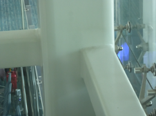
The design of rectangular HSS truss-type connections, in which the branches are laterally offset from the chord centerline, is not included in the current steel design Specification (AISC, 2016) nor in any HSS connection design guides internationally (e.g., Packer et al., 2009; Packer et al., 2010). However, branch members are sometimes offset to be flush with one side of the chord member to fulfill nonstructural needs such as aesthetics or for ease of cladding installation, as illustrated in Figure 1.

Connection Limit States
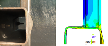
Analytical, experimental and numerical research has recently been performed on HSS X-connections under branch axial loading with the branches laterally offset to be flush with one sidewall of the chord (Bu et al., 2020). For such connections, the branch load disperses into one chord sidewall as well as into the chord connecting face. This produces a chord failure mode, which is a combination of chord sidewall failure (by web local yielding or web compression buckling) and chord face plastification (see Figure 2).

To capture this combined chord failure mode, an asymmetric rectilinear yield-line failure mechanism was proposed for the chord face in combination with a compatible deformation of the chord sidewall by considering it as a column. Using virtual work, an expression for the connection nominal strength, Pn, expressed as a force in the branch, could be obtained as (Bu et al., 2020):

In Eq. (1):
B = overall width of HSS chord member, measured 90o to the plane of the connection
Bb = overall width of HSS branch member, measured 90o to the plane of the connection
Fy = specified minimum yield stress of HSS chord member
H = overall height of HSS chord member, measured in the plane of the connection
Hb = overall height of HSS branch member, measured in the plane of the connection
K = effective length factor for buckling of sidewall
Qf = chord stress reduction factor (AISC 360-16 Eq. [K3-14])
t = design wall thickness of HSS chord member
β = branch-to-chord width ratio = Bb/B
χ = column buckling reduction factor applied to the yield stress (i.e., χ = Fcr /Fy, per AISC 360-16 Section E3) by treating the sidewall as a fixed-ended column (K = 0.65) with a length of (H – 3t) and a radius of gyration of t/√12.
γ = half of chord slenderness ratio = B/2t
To calibrate Eq. (1) for design, several hundred numerical test results (produced by a finite element model validated against laboratory tests) were compared against predictions by Eq. (1), resulting in an extremely good correlation. Under either branch compression loading or branch tension loading, a simple reliability analysis justified a resistance factor of φ = 1.0 for application to Eq. (1) in order to obtain the available connection strength (Bu et al., 2020). It is worth noting that, in the case of branch tension loading, the failure mode is web local yielding and χ = 1.0 in Eq. (1).
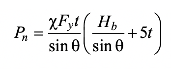
A simpler and more conservative alternative to the combined chord failure mode model above is to consider the branch force to be resisted by one chord sidewall only (without any contribution from the chord connecting face). For this single sidewall failure model, the connection nominal strength, Pn, can be predicted by:

For Eq. (2), all variables are defined above and, for design, a resistance factor of φ = 1.0 is appropriate to obtain available connection strength under either branch tension or compression loading because Eq. (2) is inherently conservative (Bu et al., 2020).
Under branch compression, the calculation of χ in either Eq. (1) or Eq. (2) can be somewhat tedious, so Kuhn et al. (2019) proposed a simplified linear buckling “curve” approximation for chord sidewall slenderness (H/t) up to 50 for the case of the sidewall having fixed ends, which calculates χ directly:

Use of the alternative χ from Eq. (3) in either Eq. (1) or Eq. (2) again requires a resistance factor of φ = 1.0 to obtain the available connection strength under branch compression loading (Bu et al., 2020).
Limitations
The two chord failure mode models, represented by Eq. (1) or the more conservative Eq. (2), either of which can be used under either branch compression or branch tension, have been validated over a range of geometric parameters bounded by 10 ≤ 2γ ≤ 35 and 0.25 ≤ β ≤ 0.85. For HSS mechanical properties, specified yield strengths up to 50 ksi have been considered.
For relatively thin branch members, a branch failure mode is possible in which branch local yielding is the limit state. A limited numerical research study (Bu et al., 2020) has shown that a conservative estimate of the connection nominal strength, Pn, expressed as a force in the branch is given by:
Pn = Fybtb (Hb + Be – 2tb)
Equation (4)
where Fyb is the specified minimum yield stress of the HSS branch member, tb is the design wall thickness of the HSS branch member, and Be is a branch transverse wall effective width term given by:


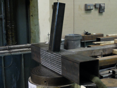
In practice, a laterally offset connection is usually secured by its surrounding structure, which provides lateral restraint. All of the above recommendations for design pertain to these ideal conditions. However, a laterally offset connection may not be able to develop its full strength if it deforms out of plane (e.g., under branch compression) and fails in a connection lateral failure mode. Experiments on laterally unrestrained offset connections (Figure 3), under branch compression, have shown that a connection strength reduction of approximately 30% relative to a laterally restrained counterpart (Wei, 2019) is likely depending on the branch length. Thus, an analysis of the supporting structure to confirm connection lateral restraint is necessary.
References
AISC. 2016. “Specification for Structural Steel Buildings,” ANSI/AISC 360-16, American Institute of Steel Construction, Chicago, IL.
Bu, X.D., Wei, F. and Packer, J.A. 2020. “Laterally Offset RHS X-Connections,” ASCE Journal of Structural Engineering, In Press, DOI: 10.1061/(ASCE)ST.1943-541X.0002864.
Kuhn, J., Packer, J.A. and Fan, Y. 2019. “Rectangular Hollow Section Webs under Transverse Compression,” Canadian Journal of Civil Engineering, Vol. 46, pp. 810-827.
Packer, J.A., Sherman, D. and Lecce, M. 2010. “Hollow Structural Section Connections,” Steel Design Guide No. 24, 1st edition, American Institute of Steel Construction, Chicago, IL.
Packer, J.A., Wardenier, J., Zhao, X.L., van der Vegte and Kurobane, Y. 2009. “Design Guide for Rectangular Hollow Section (RHS) Joints under Predominantly Static Loading,” CIDECT Design Guide No. 3, 2nd edition, CIDECT, Geneva, Switzerland, ISBN 978-3-938817-04-9.
Wei, F. 2019. “Experimental Study of Laterally Offset RHS X-Connections in Branch Axial Compression,” Master of Applied Science thesis, University of Toronto, Toronto, Canada.
December 2020