Transverse Plate-to-Square/Rectangular HSS Connections
By Jeffrey A. Packer
Bahen/Tanenbaum Professor of Civil Engineering, University of Toronto, Ontario, Canada
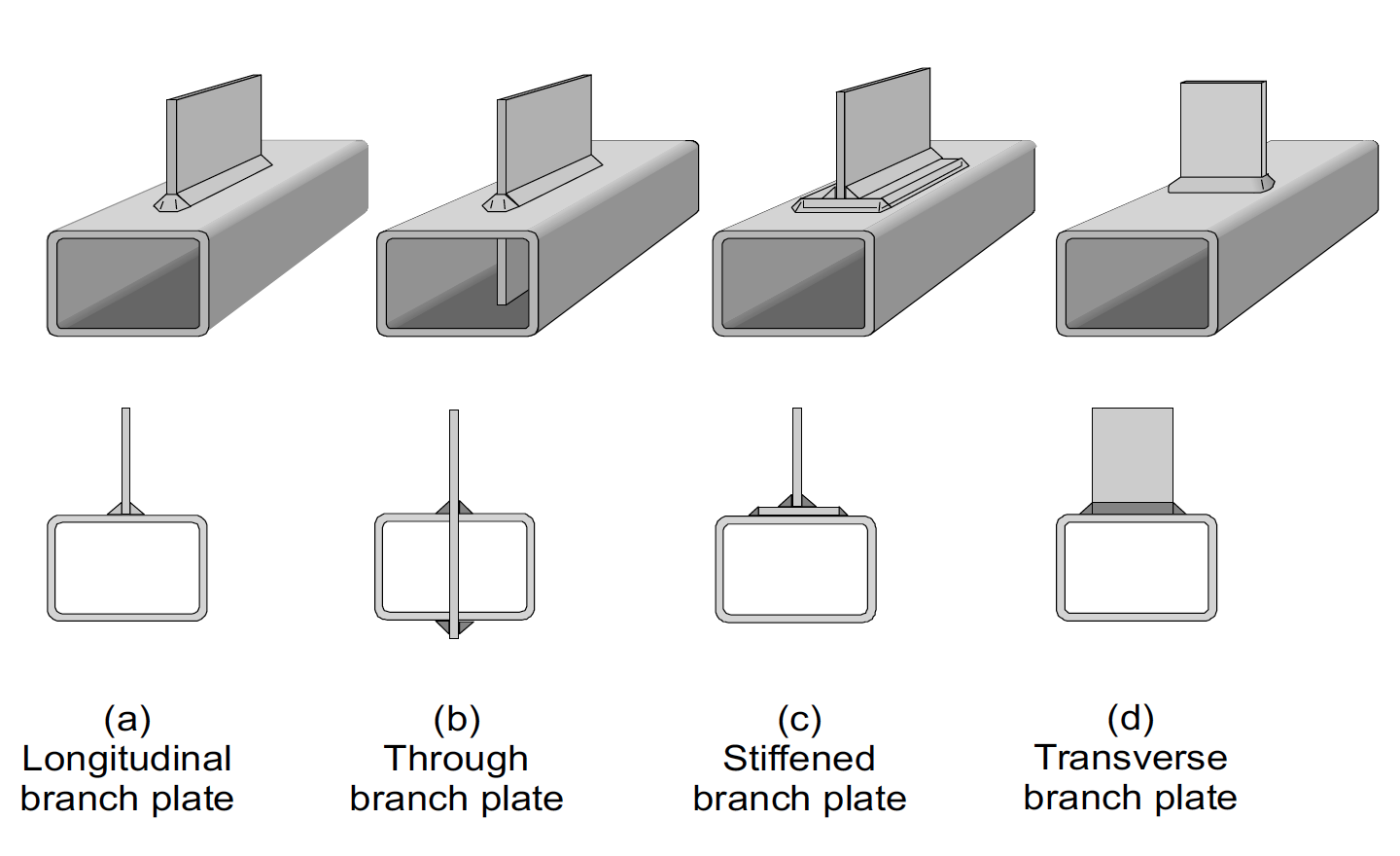
Some of the common types of plate-to-rectangular HSS welded connections are shown in Figure 1. The available strength of type (a) is relatively low, but option (b) – although being a difficult fabrication detail – is double that of option (a). If the orientation of the branch plate is optional, the transverse direction is preferable as the available strength of option (d) is generally much greater than option (a).
The transverse plate connection is also used as a representation of a wide-flange beam-to-HSS column moment connection. The moment in the beam can be considered to produce a force couple in the two beam flanges, hence the moment capacity of such a beam-to-column connection can be conservatively computed as the available strength of one plate-to-HSS connection multiplied by the distance between the centers of the upper and lower flanges. The compression flange (plate) connection should be chosen as this potentially involves consideration of additional limit states involving failure of the HSS column side walls.
Limit States
The possible limit states for transverse plate-to-HSS welded connections are as follows, with reference to particular equations in the AISC Specification (AISC, 2010):
1. Plastification of the HSS connecting face.
The available strength for this limit state can be determined by a rectilinear yield line pattern, which will be analogous to a HSS-to-HSS 90o T- connection with a branch of low Hb, as given by AISC 360-10 Table K2.2. This limit state is possible for any branch plate-to-HSS width ratio, β, below 1.0. Hence,
Rn = Fy t2 [ 2η/(1-β) + 4/(1-β)0.5 ] Qf
Equation (K2-7)
where η = tp/B. Since η will be a small value, one can approximate Eqn. (K2-7) by the following,
Rn ≥ Fy t2 [ 4/(1-β)0.5 ] Qf
Equation (K2-7A)
Although a yield line solution is a theoretical upper bound, it is valid only for small deflections and neglects substantial membrane forces and strain hardening that serve to provide an ultimate capacity far in excess of the plastic mechanism solution. Thus, the maximum resistance factor (φ=1.0) is associated with a yield line solution because the latter principally serves to restrict deformations and is a very conservative predictor of ultimate capacity.
2. Local yielding of the branch plate.
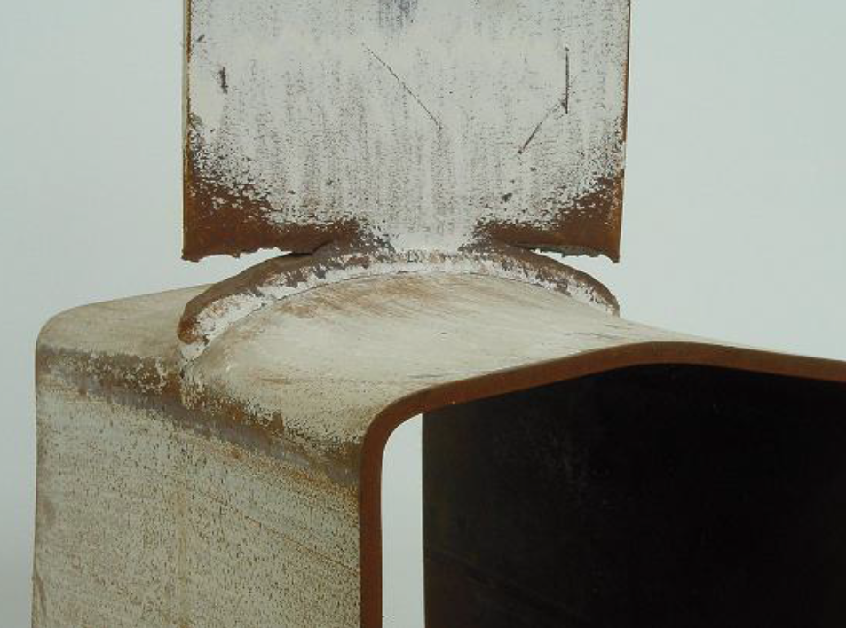
This limit state, wherein parts of the branch plate yield (and hence fail) prematurely (see Figure 2) at a load less than the gross area multiplied by the yield stress, is caused principally by the flexibility of the base (HSS face) to which the plate is attached, rendering only part of the plate width as “effective”. This plate-to-HSS “effective width” phenomenon was studied in the late 1970s/early 1980s and is encapsulated in the IIW (1989) recommendations. This limit state is possible for any β ratio and, in AISC (2010) terminology, is given by
Rn = [10/(B/t)] Fy t Bp ≤ Fyp tp Bp
Equation (K1-7)
or
Rn = 10Fy t2 β ≤ Fyp tp Bp
Equation (K1-7A)
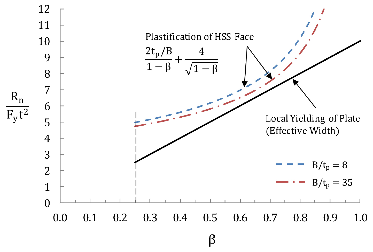
It is interesting, at this stage, to compare the simple solutions for the above two limit states. Assuming that the HSS normal stress effect is negligible (Qf = 1.0), non-dimensional connection available strengths from Equations (K2-7) and (K1-7) are plotted in Figure 3 as a function of the branch plate-to-HSS width ratio, β. It can be seen that Plastification of the HSS connecting face never governs, and for this reason it was omitted as a limit state check in international design recommendations for transverse plate-to-HSS connections in the 20th century (e.g. Packer et al. (1992), Packer and Henderson (1997)) and also in Table K1.2 of AISC 360 (2010), since the latter was based on these CIDECT/IIW recommendations.
Later, as more interest in the influence of the HSS normal stress level on the connection strength developed (represented by the function Qf), it became apparent that it was theoretically possible for the Plastification of the HSS connecting face limit state to govern, if Qf <1.0 and β and B/tp had particular values. The separation of the actual resistances for the two failure modes shown in Figure 3 is even greater because of the different resistance factors assigned (φ=1.0 for HSS plastification, and φ=0.95 for local yielding of the plate). Plastification of the HSS connecting face has hence been included as a viable limit state for transverse plate-to-HSS connections in very recent international design recommendations (e.g. CIDECT Design Guide No. 3 (Packer et al. (2009) and ISO (2013)), albeit with a modernized Qf function. Moreover, the Plastification of the HSS connecting face check will be included as a limit state check for such connections in the forthcoming AISC Specification (AISC, 2016).
3. Shear yielding (punching) of the HSS connecting face.
Transverse punching shear is a possible failure mode around any local load point . The available strength can be computed as the von Mises shear yield stress (rounded to 0.6Fy) multiplied by the shear area (HSS thickness multiplied by the punching shear length). The punching shear length may be less than the footprint perimeter around the transverse plate because of the “effective width” phenomenon also taking place in the HSS connecting face. Allowing for this transverse effective width, Bep , and discounting the presence of any possible fillet weld leg size, the Shear yielding (punching) available strength is given by
Rn = 0.6Fy t(2tp + 2Bep ), where Bep = 10Bp /(B/t) ≤ Bp
Equation (K1-8)
or
Rn = Fy t2 (12β + 1.2tp/t), subject to Bep ≤ Bp
Equation (K1-8A)
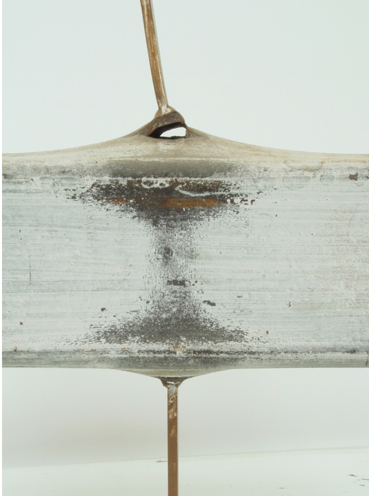
A simplification of Eqn. (K1-8A) would be Rn ≥ 12Fy t2 β which, if plotted on Figure 3, would lie above the Local yielding of the branch plate line, for all β. Both Eqns. (K1-7A) and (K1-8A) have upper limit caps and both are assigned the same resistance factor of φ=0.95, and it can be shown that (K1-8A) will not control for normal parameter combinations, such as Fyp = Fy and tp ~ t. This limit state of Shear yielding (punching) also has to be physically possible and the branch plate must be able to pull out a patch of the HSS connecting face, thus the branch plate width Bp must be ≤ (B – 2t). The limit state has also been observed, in laboratory experiments, to often occur in conjunction with flexure of the HSS connecting face (see Figure 4); thus, a combined failure mode – consisting of both Plastification of the HSS face + Shear yielding (punching) of the HSS connecting face – has been mooted. Davies and Packer (1982) derived a solution for such a combined failure mechanism but it was too complex for routine design and design recommendations have opted instead for discrete individual limit state checks. Importantly though, Davies and Packer (1982) showed that the formulation to capture Local yielding of the branch plate, Eqn. (K1-7), represented a lower bound to both their combined plastification-and-punching mechanism as well as experimental results, further substantiating the discussion above regarding these three failure modes.
4. Local yielding of HSS side walls.
This limit state, shown in Figure 4, can occur with the branch plate loaded in either tension or compression when β is close to 1.0. It is manifested by yielding of the two HSS side walls, or webs, along a short dispersed load length directly beneath the branch plate. If the load is dispersed from an initial bearing length to the bottom of the HSS corner radius (analogous to dispersion to the k-line in a W-section), at a dispersion slope of 2.5:1, then the total available yield strength for the two webs is
Rn = 2Fy t (5k + tp ), where k = outside corner radius
Equation (K1-9) and (J10-2)
5. Local crippling of HSS side walls.
This limit state, pertaining to branch compression load only, covers buckling failure of the two side walls when β is close to 1.0. For a single concentrated force, corresponding to a plate-to-HSS T-connection, the available strength differs from international HSS connection recommendations and is adapted by AISC from the web local crippling expression for a W-section web:
Rn = 1.6t2 [1 + 3tp/(H – 3t)] [EFy ]0.5 Qf
Equation (K1-10) and (J10-4)
Similarly, for a pair of concentrated forces, corresponding to a plate-to-HSS Cross- (or X-) connection (see Figure 5), the available strength differs from international HSS connection recommendations and is adapted by AISC from the web local buckling expression for a W-section web:
Rn = [48t3 /(H – 3t)] [EFy ]0.5 Qf
Equation (K1-11) and (J10-8)
Limits of Applicability
Table K1.2A of AISC 360-10 gives a range of validity for a number of geometric and mechanical properties for which all of Table K1.2 would be valid. All limits would not apply to all the limit states in Table K1.2. For transverse plate connections, Eqns. (K1-7) and (K1-8), corresponding to Limit States 2 and 3 above, contain effective width terms which have been derived from research – predominantly experimental – in which the wall slenderness limits (B/t and H/t ≤ 35) and width ratio (1.0 ≥ Bp /B ≥ 0.25) represented the bounds of the test data at the time. Similarly, the mechanical property limitations also represented the limits of test evidence for Limit States 2 and 3, at the time. As noted previously, Limit State 1 is a generic analytical solution. Limit State 4 is very similar to international recommendations and is fundamental to most steel design standards. Limit State 5 available strength expressions (and their associated resistance factors) are borrowed from W-section limit states given in Chapter J of AISC-360; these formulas are quite different to all former and current international HSS recommendations and thus arguably not restricted by HSS test data bounds given in Table K1.2A.
References
AISC. 2010. “Specification for Structural Steel Buildings”, ANSI/AISC 360-10, American Institute of Steel Construction, Chicago, IL.
AISC. 2016. “Specification for Structural Steel Buildings”, ANSI/AISC 360-16, American Institute of Steel Construction, Chicago, IL.
Davies, G. and Packer, J.A. 1982. “Predicting the Strength of Branch Plate – RHS Connections for Punching Shear”, Canadian Journal of Civil Engineering, Vol. 9, pp. 458-467.
IIW. 1989. “Design Recommendations for Hollow Section Joints – Predominantly Statically Loaded”, 2nd edition, IIW Doc. XV-701-89, International Institute of Welding, Paris, France.
ISO. 2013. “Static Design Procedure for Welded Hollow-Section Joints – Recommendations”, ISO 14346:2013(E), International Standards Organisation, Geneva, Switzerland.
Packer, J.A. and Henderson, J.E. 1997. “Hollow Structural Section Connections and Trusses – A Design Guide”, 2nd edition, Canadian Institute of Steel Construction, Toronto, Canada, ISBN 0-88811-086-3.
Packer, J. A., Wardenier, J., Kurobane, Y., Dutta, D. and Yeomans, N. 1992. “Design Guide for Rectangular Hollow Section (RHS) Joints under Predominantly Static Loading”, CIDECT Design Guide No. 3, 1st edition, Comité International pour le Développement et l’Étude de la Construction Tubulaire (CIDECT) and Verlag TÜV Rheinland GmbH, Köln, Germany, ISBN 3-8249-0089-0.
Packer, J. A., Wardenier, J., Zhao, X.-L., van der Vegte, G.J. and Kurobane, Y. 2009. “Design Guide for Rectangular Hollow Section (RHS) Joints under Predominantly Static Loading”, CIDECT Design Guide No. 3, 2nd edition, Comité International pour le Développement et l’Étude de la Construction Tubulaire, Geneva, Switzerland, ISBN 978-3-938817-04-9.
January 2015