Through Plate-to-Round HSS Connections
By Jeffrey A. Packer
Bahen/Tanenbaum Professor of Civil Engineering, University of Toronto, Ontario, Canada
Design recommendations for longitudinal and transverse branch (or gusset) plate T-connections, with the plate subjected to a quasi-static load axial to the plate, are now well-established in modern steel design codes, specifications and international guides, including AISC 360 Chapter K (AISC, 2010). An important feature of all these recommendations, however, is that the connection design capacity is independent of the sense of the branch plate load; i.e., the same connection strength is assumed for both branch tension and compression loading cases, with a lower bound being taken to accommodate both load cases.
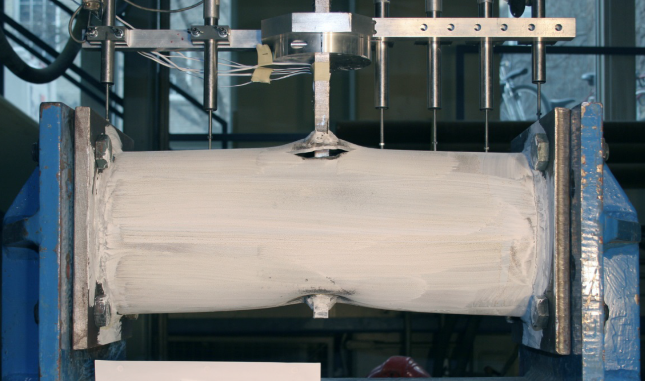
A widely used stiffening and strengthening method is a plate-to-tube connection where the branch plate is slotted through the HSS and welded to two opposing faces (see Figure 1). This has the advantage of engaging much more of the cross section in load resistance, and hence has a higher capacity than the equivalent branch plate connection, but the through plate connection is a more difficult and more expensive fabrication procedure. Also, a part of the through plate protrudes beyond the far side of the HSS (Figure 1), which may affect connections to that side of the HSS.

Research on longitudinal through plate connections to rectangular/square HSS members (Kosteski and Packer, 2003) showed that the connection strength was double that of the equivalent branch plate connection, because two flat HSS faces were engaged in relatively independent but identical flat-plate flexural mechanisms. This “double strength” has hence been adopted for square and rectangular HSS longitudinal through plate connections in numerous codes, specifications and guides (Kurobane et al., 2004; Packer et al., 2009; AISC, 2010; Packer et al., 2010; Wardenier et al., 2010), but none of these offer a solution for round HSS through plate connections.
A recent experimental study (Figure 2) of through plate-to-round HSS connections (Voth and Packer, 2012a) indicated that through plate-to-hollow section connection behavior is actually comprised of two independent mechanisms: one in compression and one in tension, which occur on opposite sides of the hollow section chord during load application. Preliminary examination of this behavior also illustrated that the capacity of a through plate connection is approximately the summation of the capacities of a branch plate-to-round HSS connection tested in tension and a branch plate-to-round HSS connection tested in compression, provided that connection geometry for the branch connection and the through connection are similar. The dual mechanism for plate-to-round HSS connections differs from the approach that has been previously applied to plate-to-rectangular HSS connections, where for the latter the same failure mechanism is present on both the top and bottom connection faces.

Only a limited number of experimental and numerical tests were performed for through plate-to-round HSS T-connections (Voth and Packer, 2012a), with the experimental tests serving to verify the finite element (FE) models. Hence, a parametric FE study was performed (Voth and Packer, 2015) to explore an expanded range of geometric parameters for such connections, with the aim of combining tension and compression branch plate-to-round HSS capacities to develop through plate-to-round HSS connection capacity.
Design Resistance of Branch Plate T-connections
Branch plate-to-round HSS connection axial resistance is currently determined in practice by Equations (K1-1) and (K1-2) in Table K1.1 of AISC 360 (2010). The connection available strength expressions take the form:
Rn = Fy t2 Qu Qf /sinӨ
Equation (1)
where Qu is a “partial design strength function” that predicts non-dimensionalized connection resistance (RnsinӨ/Fyt2) without chord axial stress, and Qf is a “chord stress function” that may reduce connection resistance because of the presence of compressive normal stress in the chord connecting face.
An extensive experimental and numerical research project has been recently conducted (Voth and Packer, 2012a, 2012b; 2012c) for X- and T-type branch plate-to-round HSS connections in an effort to re-evaluate the partial design strength function, Qu. The study again confirmed that the behavior of branch plate connections tested under plate axial compression load varied significantly with respect to connections under branch plate axial tension load. Since the capacity of the tension-only connections was found to be very under-utilized in current guidelines, a regression analysis of the numerical results was undertaken and new Qu functions were developed for branch plate-to-round HSS T-connections, as follows:
| Qu,90,C = 2.9(1 + 3β/2).γ0.35 | , for transverse (90o) plate in compression | Equation (2) |
| Qu,90,T = 2.6(1 + 2.5β/2).γ0.55 | , for transverse (90o) plate in tension | Equation (3) |
| Qu,0,C = 7.2(1 + 0.7η/) | , for longitudinal (0o) plate in compression | Equation (4) |
| Qu,0,T = 10.2(1 + 0.6η/) | , for longitudinal (0o) plate in tension | Equation (5) |
A lower bound resistance factor of φ = 0.85 was found to be adequate, for application to LRFD.
Application to Through Plate T-connections
The general behavior of a through plate-to-round HSS T-connection has been established to be the approximate addition of tension and compression branch plate-to-round HSS connection behaviors. Thus, it is logical that the function, Qu, for through plate connections could be given by:
| Qu = Qu,90,C + Qu,90,T | , for transverse through plate connections | Equation (6) |
| Qu = Qu,0,C + Qu,0,T | , for longitudinal through plate connections | Equation (7) |
where Qu,90,C, Qu,90,T, Qu,0,C and Qu,0,T are given by Equations (2) to (5) respectively.
Equations (6) and (7) were shown to give reasonable lower-bound approximations for ultimate capacity (Voth and Packer, 2015) and hence can be conservatively adopted to estimate through plate connection capacity. It is thus recommended that the available strength of axially loaded through plate-to-round HSS 90o T-connections be determined by:
Transverse: Rn = Fy t2 [ 2.9(1 + 3β/ 2).γ0.35 + 2.6 (1 + 2.5β/ 2).γ0.55 ]Qf
Equation (8)
Longitudinal: Rn = Fy t2 [ 7.2(1 + 0.7η/ ) + 10.2 (1 + 0.6η/ )]Qf
Equation (9)
where Qf can be taken from AISC 360-10 Table K1.1. For LRFD a resistance factor of φ = 0.85 is recommended (or Ω = 1.76 for ASD) as previously for branch plate T-connections, on which Equations (8) and (9) are based (Voth and Packer, 2012c). So-called “effective” values for the non-dimensional parameters β/ and η/ are used in the above equations, but the use of the regular variables β and η (which have lower values since they do not include the weld sizes) is a conservative alternative and would be more common in practice.
Equations (8) and (9) are empirical and are verified for the key parameter ranges: 0.2 ≤ β ≤ 0.6; 0.2 ≤ η ≤ 2.5; 20 ≤ 2γ ≤ 46. Equations (8) and (9) provide, for the first time, a means of enabling through plate-to-round HSS connections to be designed, taking proper advantage of their very favourable strength characteristics without resorting to treating them punitively as branch plate-to-round HSS connections. The considerable strength advantage provided by the through plate Equations (8) and (9), relative to AISC 360 existing equations for their branch plate counterparts, is illustrated in Table 1.

Notation
Bp, Bp/ = nominal, effective width of plate (Bp/ = Bp + 2w0), 90o to plane of the connection
D = outside diameter of round HSS
Fy = yield stress of HSS member
lb, lb/ = nominal, effective bearing length of plate (lb/ = lb + 2w0), parallel to the axis of the HSS
Qf = chord stress influence function
Qu = partial strength function
Rn = nominal strength of connection, expressed as an axial force in the branch plate
t = thickness of HSS chord member
w0 = measured weld leg length along the HSS chord
β, β/ = nominal, effective connection width ratio (β = Bp/D, β/ = Bp/ /D) for transverse plates
γ = chord radius-to-thickness ratio (= D/2t)
φ = resistance factor
Ω = safety factor
η, η/ = nominal, effective connection length ratio (η = lb/D, η/ = lb/ /D) for longitudinal plates
Ө = included angle of inclination between branch and chord
References
AISC. 2010. “Specification for Structural Steel Buildings”, ANSI/AISC 360-10, American Institute of Steel Construction, Chicago, IL, USA.
Kosteski, N. and Packer, J.A. 2003. “Longitudinal Plate and Through Plate-to-HSS Welded Connections”, ASCE Journal of Structural Engineering, Vol. 129, No. 4, pp. 478-486.
Kurobane, Y., Packer, J.A., Wardenier, J. and Yeomans, N. 2004. “Design Guide for Structural Hollow Section Column Connections”, CIDECT Design Guide No. 9, Comité International pour le Développement et l’Étude de la Construction Tubulaire, Geneva, Switzerland.
Packer, J.A., Sherman, D. and Lecce, M. 2010. “Hollow Structural Section Connections”, Steel Design Guide No. 24, American Institute of Steel Construction, Chicago, IL, USA.
Packer, J.A., Wardenier, J., Zhao, X.-L., van der Vegte, G.J. and Kurobane, Y. 2009. “Design Guide for Rectangular Hollow Section (RHS) Joints under Predominantly Static Loading”, CIDECT Design Guide No. 3, 2nd edition, Comité International pour le Développement et l’Étude de la Construction Tubulaire, Geneva, Switzerland.
Voth, A.P. and Packer, J.A. 2012a. “Branch Plate-to-Circular Hollow Structural Section Connections. I: Experimental Investigation and Finite-Element Modeling”, ASCE Journal of Structural Engineering, Vol. 138, No. 8, pp. 995-1006.
Voth, A.P. and Packer, J.A. 2012b. “Branch Plate-to-Circular Hollow Structural Section Connections. II: X-Type Parametric Numerical Study and Design”, ASCE Journal of Structural Engineering, Vol. 138, No. 8, pp. 1007-1018.
Voth, A.P. and Packer, J.A. 2012c. “Numerical Study and Design of T-type Branch Plate-to-Circular Hollow Section Connections”, Engineering Structures, Vol. 41, pp. 477-489.
Voth, A.P. and Packer, J.A. 2015. “Numerical Study of Through Plate-to-CHS Connections”, 15th International Symposium on Tubular Structures, Rio de Janeiro, Brazil, 8 pp.
Wardenier, J., Packer, J.A., Zhao, X.-L. and van der Vegte, G.J. 2010. “Hollow Sections in Structural Applications”, 2nd edition, Comité International pour le Développement et l’Étude de la Construction Tubulaire, Geneva, Switzerland.
April 2015