HSS Splice Design Examples | Part 1: Rectangular Column Field Welded Moment Splices
By Mike Manor, PE, MLSE
April, 2025
Hollow Structural Section (HSS) columns are applicable to many design situations and can be used in more building types than just single-story applications. HSS columns are an excellent option in multi-story buildings, as evidenced in this linked multi-story case study. When used in multi-story buildings, consideration must be made for the maximum column length limitations for shipment to the building site. When the column lengths exceed shipment limitations, column splices are required to complete the installation. For guidance on splices in gravity-only columns, refer to the STI “HSS Column Splices” and “HSS Splices” articles as well as the AISC 360-22 Steel Specification and 16th Edition Steel Manual. However, when it comes to splices for columns that have bending moment due to frame action, there are not many resources available. To fill the gap, this article is the first of a multi-part series providing design examples specifically for rectangular HSS column splices with bending moment.
The two examples in this article will focus on demonstrating field welded splice options. The first example uses a directly welded splice, while the second example uses splice plates on four sides of a rectangular HSS column. Each example will provide commentary along the way to provide pertinent information to consider during the design process. Future parts to this article series will consider field bolting splice options including side plates and end plates, among other options, while considering both traditional structural bolts as well as blind structural fasteners that must be installed from one side only.
Example #1: Directly Welded HSS Column Bearing Splice
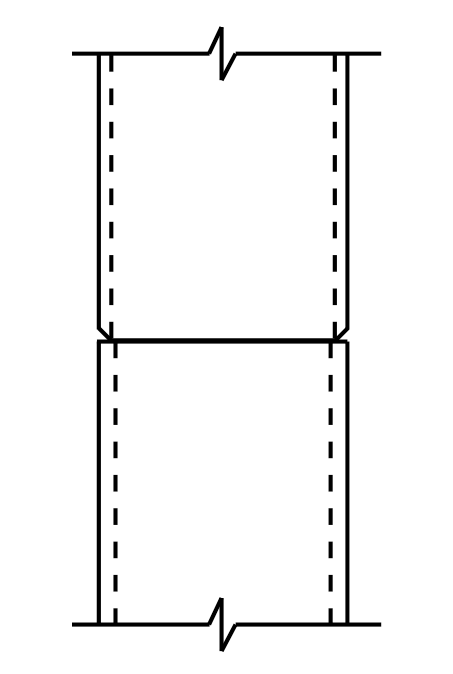
Directly welded splices are a common type of column splice but are often specified with complete joint penetration (CJP) welds to fully develop the column section, which is often unnecessary. CJP welds require extensive installation effort, backing bars, and additional inspections, making them unnecessarily complex and costly. As an alternative, partial joint penetration (PJP) welds are more economical since they can be installed without backing bars or the extra inspections. PJP welds generally develop adequate capacity for the transfer loads present at the splice and in some cases can still develop the full column section. Therefore, this example will explore using PJP weld splices as a more practical alternative.
Given:
- HSS material: ASTM A500 Gr. C (Fy = 50 ksi, Fu = 62 ksi)
- Upper column: HSS 10x10x1/2
- Lower column: HSS 10x10x5/8
- Finish columns to bear
- Weld electrodes: FEXX = 70 ksi
- Axial load: Pu = 500 k
- Factored moment load: Mu = 40 k ∙ ft = 480in ∙ k
- Factored shear load: Vu = 10 k
Determine the weld required for the loads present at this column splice.
HSS Geometry
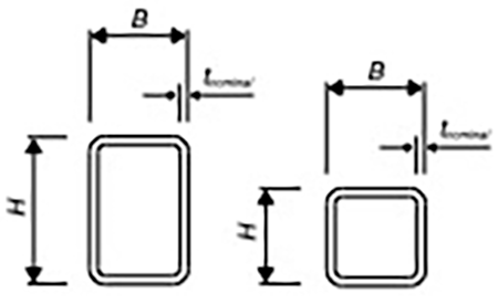
The thinnest element in the splice will determine the geometry of the weld preparation as will be demonstrated later in the example. Secondly, the minimum weld size in the AISC 360-22 Chapter J table J2.3, Minimum Effective Throat of Partial-Joint-Penetration Groove Welds, requires a minimum weld size based on the material thickness of the thinner part joined by the weld. Therefore, base the weld design on the upper HSS column in the splice. Refer to Figure 1 for variable definitions.
HSS10x10x1/2
B = 10 in. H = 10 in tnominal = 0.5 in tdesign = 0.465 in
Partial Joint Penetration (PJP) Weld
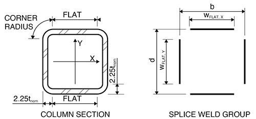
Design calculations for the weld will be based solely on the workable flats of the rectangular HSS section, ignoring the weld at the corner radius. This is because welding in regions of high cold working, such as the HSS corner radius, presents challenges that American Welding Society AWS D1.1 welding code does not address. Per the AISC 16th Edition Steel Manual Part 1: Structural Products subsection for HSS, the workable flat is determined by subtracting an assumed corner radius of 2.25tnominal from both the (B) width and depth (H) of the section (see Figure 1). The nominal thickness, tnominal, is the specified thickness of an HSS member.
Width of flats: wflat,X = wflat,Y = B – 2 * 2.25tnominal = 10 in – 2(2.25)(0.5in) = 7.75in
Total weld length: lweld = 2 * wflat,X + 2 * wflat,Y = 2(7.75in) +2(7.75in) = 31in
Per AISC 360-22 Tables J2.1 and J2.3, the minimum effective weld throat for a PJP groove weld is based on the material thickness of the thinner part being joined and the installation position of the weld. The welds for these column splices will be installed in the horizontal position. Since the upper column thickness tnominal = 0.5 in, the minimum effective weld throat size is Smin = 3/16 in . Assuming the PJP weld will be filled flush to the outside face of the HSS wall, the centerline of the weld will be inset by a distance equal to half of the effective weld size on all four sides of the section for calculation.
The strength required for the PJP weld is determined in accordance with AISC Section J2.4 and Table J2.5. In the table, there are different strength requirements for the welds at the column splice depending on how the compressive forces are transferred across the splice. When a compression connection is not specifically required to transfer load in bearing, then the welds must be designed to transfer the compressive load across the joint. Per section J1.4a, columns finished to bear at splices only need “sufficient connectors to hold all parts in place.” In this case, Table J2.5 notes the “compressive stress is permitted to be neglected in design of welds joining the parts.” This means the splice welds only need to be designed for the tension force from the moment transfer.
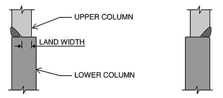
For column bearing splices, the AISC 16th Edition Steel Manual Table 14-3 provides guidance for design in accordance with the AISC 360 Specification as well as erection requirements of typical column splices. The column splice chosen for this design example is per Table 14-3 Case X. The description for this case references a minimum land distance (see Figure 4) for bearing of the upper column on the lower column during erection that will also transfer the column splice compression loads through bearing. The land distance is referenced in Table 14-3 Case VIII as a minimum 1/4 in. The bearing strength of steel with surfaces finished to bear is significantly greater than the nominal yield strength due to post yield strength gains as deformation increases.
As noted in the STI HSS Weld Splices article, the corner radius of HSS members varies based on the thickness of the upper and lower columns. Additionally, the radius will vary slightly between producers. Thus, the corner radiuses may not always align between the upper and lower columns. To conservatively verify the bearing strength, use the land area at the flats only.
Bearing Area:
Assume tland = 1/4 in
Apb = tland (2wflat,X + 2wflat,Y) = 1/4 in[(2)(7.75in) + (2)(7.75in)] = 7.75 in2
Bearing strength:
ϕRn=1.8ϕFyApb = (1.8)(0.75)(50ksi)(7.75 in2) = 523k AISC 360-22 Equation J7-1
This conservative estimate exceeds the axial load of for this example. However, if this were not enough capacity, the bearing strength could be increased by taking a closer look at how much additional area of overlap can be included at the four corners. A second option would be to design the PJP welds to transfer the additional compression load.
Since the 1/4 in land width provides adequate bearing strength to transfer the column axial load, the geometry of the PJP weld can be determined. There are many PJP weld options available to accomplish the connection based on a combination of the welding process and joint preparation. Part 8 of the AISC 16th Edition Steel Manual lists many available PJP weld options toward the end of Table 8-2 which include four welding process options of shielded metal arc welding (SMAW), gas metal arc welding (GMAW), flux core arc welding (FCAW), and submerged arc welding (SAW). For more information on weld processes and PJP weld types, refer to the Know Your HSS Welds article in Structure Magazine and the AISC Design Guide 21: Welded Connections – A Primer for Engineers. Depending on the steel fabricator chosen for the project, each company may have different weld preferences based on shop standards and equipment for the most economical weld installation. If the fabricator is not known at the time of design, including the minimum weld effective throat required will aid the fabricator in deciding the best weld option for the project.
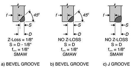
From AISC 16th Edition Steel Manual Table 8-2, Figure 5 shows three possible weld options for this example. In the figure, parts a and b show the top column prepared with a bevel at an angle of 45° while part c is prepared with a curved groove. The top column will be prepared so that the welder in the field can install the weld in a horizontal position. The first step in designing the weld size is to determine the size of the root face of the weld which is the area of steel contact adjacent to the weld (dimension f in Figure 5). The root face f = tland = 1/4 in is larger than the required fmin = 1/8 in and is adequate for all three cases.
Now the effective weld size can be established. Depending on the weld process, the weld may or may not completely fuse the metal of the two HSS members at the root of the weld. The weld root is the point of the weld adjacent to the root face. When fusion of the parts welded is not complete, a Z-Loss factor is applied meaning that a portion of the preparation depth, D, is discounted for the effectives weld size, . Based on the preparation geometry, the maximum available weld size, Smax, is calculated using the design thickness, tmax .
Weld option a:
Sa,max = tdesign – f – 1/8in = 0.465in – 1/4in – 1/8in = 0.09in
Round down to Sa,max = 2/32in = 1/16in <Smin = 3/16in → does not meet the PJP weld requirement.
Weld options b and c:
Sb,max = S c,max = tdesign – f = 0.465in – 1/4in = 0.215in
Round down to Sb,max = 6/32in = 3/16in = Smin = 3/16in → does meet the PJP weld requirement and both are viable options.
Weld Group Maximum Stress
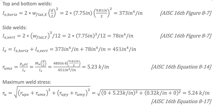
Use the Elastic Method in Part 8 of the AISC 16th Edition Steel Manual with eccentricity normal to the plane of the faying surface to determine strength of the weld group shown in Figure 3.
b = B – S = 10 in – 3/16 in = 9.81in
d = H – S = 10 in – 3/16 in = 9.81in
from above, wflat,X = wflat,Y = 7.75in and lweld = 31in

Weld stress due to moment: determine lx for weld group
PJP Available Weld Strength
[AISC 360-22 Section J2.4 & Table J2.5]
The strength of the weld is determined per the equations of section J2.4 with guidance on variables in the reference to Table J2.5, Available Strength of Welded Joints. As previously described in this article, the column is finished to bear, so the compressive stress is permitted to be ignored as noted in pertinent table row. Thus, only the tension normal to the weld axis needs to be checked. For demonstration purposes in this example, the weld will be designed for the tension due to the moment at the splice rather than the net tension considering the compression load in the column.
Effective are of weld: Awe = S * Lweld = 3/16in * 1in = 3/16 in2/in
Weld electrode filler metal classification strength: FEXX = 70ksi
Nominal weld stress: Fnw = 0.6FEXX = 0.6 * 70ksi = 42ksi
Weld strength:
ϕRn,w = ϕFnwAwe = (0.8)(42ksi)(3/16 in2/in) = 6.6k / in [AISC 360-22 Equation J2-3]
Base Metal Strength at Weld
[AISC 360-22 Section J2.4 & Table J2.5]
The calculation for the strength of the base metal at the weld is determined per the equations of section J2.4 with guidance on variables in the reference to Table J2.5: Available Strength of Welded Joints. J2.4 notes the base metal strength is based on the limit state of tensile rupture. Additionally, the table J2.5 row for tension normal to the weld axis refers to section J4, Affected Elements of Members and Connecting Elements, for the area of the base metal. Section J4.1, Strength of Elements in Tension, provides the calculation for tensile rupture of connecting elements with the effective net area defined by section D3, Effective Net Area, and Table D3.1, Shear Lag Factors for Connections to Tension Members. Since the weld is attached to all portions of the HSS section, use Table D3.1 Case 1.
Nominal base metal stress: FnBM = Fu = 62ksi
Base metal area: ABM = Ae =AnU = tdesign * Lweld * U = (0.465in)(1in)(1.0) = 0.465 in2 [AISC 360-22 Equation D3-1]
Base metal strength at weld: ϕRn,BM = ϕFnBMABM = (0.75)(62ksi)(0.46 in2) = 21.6k / in [AISC 360-22 Equation J2-2]

Use a PJP weld with an effective weld size effective weld size using the GMAW weld procedure with a bevel groove or the SMAW weld procedure with a J weld. Finish upper and lower columns to bear.

Note that this design is based on design loads only. Erection requirements per the Occupational Safety and Health Administration (OSHA) and the AISC 303-22 Code of Standard Practice for Steel Buildings and Bridges need to be considered prior to production of final shop drawings.
Example #2: Welded Side Plate HSS Column Bearing Splice
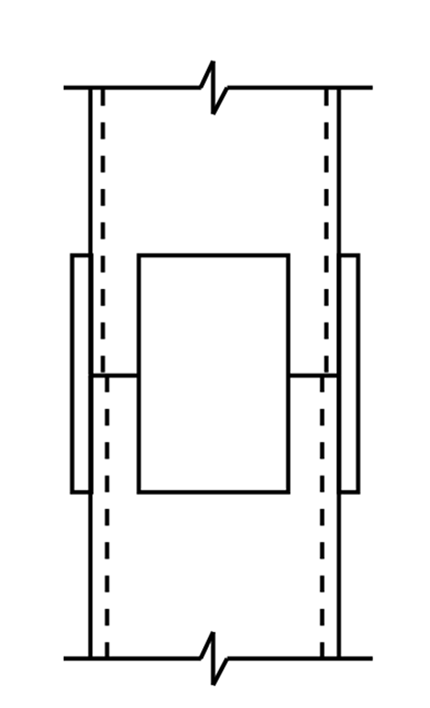
This example will explore using external splice plates on all four sides of the HSS column. This type of splice requires the upper and lower columns to have the same nominal outside dimensions, but the thickness of the HSS wall can vary. When the splice is for gravity-only loading conditions, the compressive forces are transmitted through direct bearing and the splice plates merely need to hold the columns in place. These plates are typically welded to the lower column with fillet welds in the fabrication shop which serve as convenient guides during field installation, ensuring proper alignment with minimal adjustment for the final field fillet weld to the upper column to complete the splice. If needed, these welds can transfer tension forces due to moment transfer or net uplift. This splice connection requires minimal fabrication preparation work compared to directly welded complete or partial joint penetration (CJP or PJP) welds, and fillet welds are much easier to install in the field with fewer welder qualification requirements. The reduction in both fabrication shop time and easier field installation provides a low-cost splice option.
Given:
- HSS material: ASTM A500 Gr. C (Fy = 50 ksi, Fu = 62 ksi)
- Upper column: HSS 10x10x1/2
- Lower column: HSS 10x10x5/8
- Finish columns to bear
- Plate material: ASTM A572 Grade 50 (Fy = 50 ksi, Fu = 65 ksi)
- Weld electrodes: FEXX = 70 ksi
- Axial load: Pu = 500 k
- Factored moment load: Mu = 40 k ∙ ft = 480 in ∙ k
- Factored shear load: Vu = 10 k
Determine the size of side plates and weld required for the loads present at this column splice.
HSS Geometry
An HSS column splice with welded side plates provides a bearing connection to transfer the compressive load without any need for preparation of the column end for weld other than the standard finish to bear. Depending on the corner along the full area of the HSS flats.
The thinnest element in the splice will determine the minimum fillet weld size per the requirement of AISC 360-22 Chapter J table J2.4, Minimum Size of Fillet Welds. The splice in this example is comprised of the upper column, lower column, and splice plates. Since the thickness of the splice plates is not yet known, either the splice plates or the thinner column will determine the minimum weld size. However, the thicker column will need to be considered for determining the maximum available plate width to leave enough room to fit the fillet weld between the corner radius of the HSS and the splice plate. There are two reasons to avoid welding at the corner radius of the HSS. First, a fillet weld between the two perpendicular edges of the plate and the flat face of the HSS is easier to install while ensuring the required effective throat is met. Second, as noted in the first example, welding in regions of high cold working, such as the HSS corner radius, presents challenges that the American Welding Society AWS D1.1 welding code does not address. Therefore, both columns need to be considered. Refer to Figure 1 for variable definitions.
HSS10x10x1/2
H = 10 in. B = 10 in tnominal = 0.5 in tdesign = 0.465 in
HSS10x10x5/8
H = 10 in. B = 10 in tnominal = 0.625 in tdesign = 0.581 in
Per the AISC 16th Edition Steel Manual Part 1: Structural Products subsection for HSS, the workable flat is determined by subtracting an assumed corner radius of 2.25tnominal from both the width (B) and depth (H) of the section (see Figure 1). The nominal thickness, tnominal, is the specified thickness of an HSS member. Since the width of the flats is based on HSS thickness, the thicker column will have the narrowest flat width.
Width of flats: wflat,X = wflat,Y = B – 2 * 2.25tnominal = 10 in – 2(2.25)(0.625in) = 7.19 in
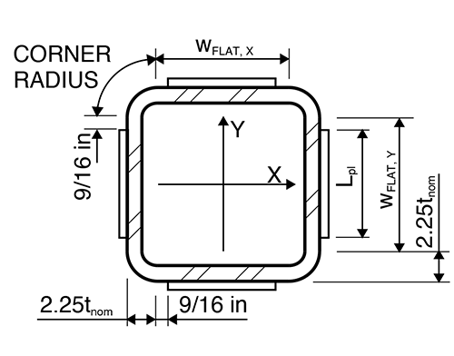
As discussed in the first example, the corner radius of the two columns may not fully align, but the bearing area of the flats will generally provide adequate bearing area to transfer the compressive forces. To demonstrate, the columns are finished to bear, which is typical for column splices, and the corner radius will conservatively be ignored in the bearing calculation. Using the width of flats from the thicker column in combination with the design thickness of the thinner column, a conservative bearing area is calculated.
Bearing Area:
Apb = tdesign (2wflat,X + 2wflat,Y) = 0.465 in [(2)(7.19 in) + (2)(7.19 in)] = 13.4 in2
Bearing strength:
ϕRn =1.8ϕFyApb = (1.8)(0.75)(50ksi)(13.4 in2) = 905k [AISC 360-22 Equation J7-1]
As described in the first example, the bearing strength is much larger than the yield strength. For comparison, the available strength in axial compression load of an HSS10x10x1/2 at an unbraced length of zero is ϕPn = 774 k per AISC 16th Edition Steel Manual Table 4-4. This conservative assumption of bearing area shows that there is always more bearing capacity available than the upper HSS column could transfer in compression showing that the side plate splice option will always be able to transfer the compressive loads directly.
Design Side Plates
The first step in designing the splice plates is establishing the maximum available plate width. In Part 8 of the AISC 16th Edition Steel Manual, the section called Minimum Shelf Dimensions for Fillet Welds can provide some guidance on how much space, , that is needed between the splice plate and HSS corner. Additionally, Table 8-12 notes that the largest fillet weld that can be installed in a single pass is wmax = 5/16 in. Using a single pass fillet weld means the welder only needs to lay a single bead of weld to reach the required weld throat. This will minimize the amount of labor time required for installing the splice plate weld keeping the installation cost to a minimum. Combining these two pieces of information together, leave a minimum shelf distance each side of the plate as:
Minimum weld shelf width:
bmax = wmax + 1/4 in = 5/16 in + 1/4 in= 9/16 in [AISC 16th Figure 8-1]
Maximum plate width:
Lpl,max = wflat,X – 2bmax = 7.19 in – 2(9/16 in) = 6.07in
Try Lpl=6 in

Use AISC 360-22 section J4.1, Strength of Elements in Tension.
Plate gross tension area: Ag = An =Lpltpl = 6tpl in2
Section J4.1 refers to section D3, Effective Net Area, and use Table D3.1, Shear Lag Factors for Tension Members. Since the splice plates are attached to all four HSS walls, there will be no shear lag and per Table D3.1 Case 1.
Plate effective net tension area: Ae = AnU = Lpltpl = 6tpl in2 [AISC 360-22 Equation D3-1]
Tensile Yielding:
ϕRn = ϕFyAg = (0.9)(50ksi)(6tpl in2 ) = 270tpl k [AISC 360-22 Equations J4-1 & J4-6]
Tensile Rupture:
ϕRn = ϕFuAe = (0.9)(65ksi)(6tpl in2) = 351tpl k nnbsp; [AISC 360-22 Equation J4-2]
Tensile yielding controls. Find the minimum plate thickness by setting this equal to the force so that

Design Side Plate Weld
Try 1/4 in fillet weld thus D = 4 sixteenths
Check column rupture strength at welds:

ϕRn = (1.392 k/in)DL = (1.392 k/in)(4) Lweld = 5.57Lweld k [AISC 16th Equation 8-2a]
Set equal to the splice plate force:

Provide vertical weld length equal to plate length.
Lweld = 3 * Lpl = 3(6 in) = 18 in > Lweld,min = 8.6 in → OK
Use PL3/8 in x 6 splice plates on all four sides of column with 1/4 in fillet welds on all edges.
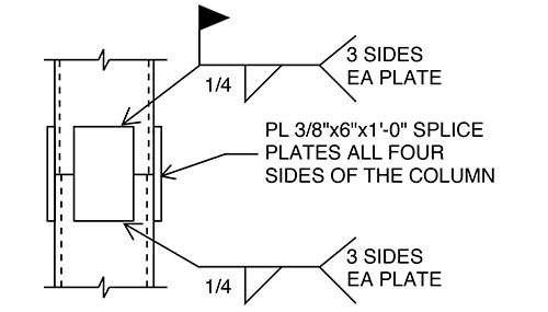
Note that this design is based on design loads only. Erection requirements per (OSHA) and the AISC 303-22 Code of Standard Practice for Steel Buildings and Bridges need to be considered prior to production of final shop drawings.
Conclusion:
In summary, this article demonstrates effective field-welded splice options for rectangular HSS columns when shipping limitations require splicing on site. The examples provided—direct welding and four-sided splice plates—offer practical guidance for constructible solutions. Future installments will expand on this foundation with field-bolted splices and innovative blind fastener systems. Combined with existing STI and AISC resources, these examples offer a comprehensive, practical approach to HSS column splice design that supports both structural performance and ease of fabrication.
References
STI Article: “HSS Column Splices” by Mike Manor, January 2018
STI Article: “HSS Splices” by Jeffrey A. Packer, July 2026
STI Article: “Design of Fillet Welds to Rectangular HSS” by Jeffrey A. Packer, June 2015
STI Article: “Welding of Hollow Structural Sections” by Jeffrey A. Packer, March/April 2012
STI Article: “Full-Capacity Welds: CJP vs. Fillet vs. Fillet-Reinforced PJP” by Jeffrey A. Packer, November 2024
STI Article: “Expert Tips for Cost-Effective HSS Specification and Fabrication” by Mike Manor and Cathleen Jacinto, April 2023
STI Document: “HSS and WF Comparative Case Study” November 2024
Structure Magazine Article: “Know Your HSS Welds” by Mike Manor and Cathleen Jacinto, February 2024
AISC Publication: “360-22: Specification for Structural Steel Buildings“
AISC Publication: “Steel Construction Manual 16th Edition”
AISC Publication: “Design Guide 21: Welded Connections – A Primer for Engineers”
AISC Publication: “Design Guide 24: Hollow Structural Section Connections (Second Edition)”