Understanding Local Yielding Due to Uneven Load Distribution
By Mike Manor, PE, MLSE
Technical Consultant, Steel Tube Institute
Local yielding at connections involving HSS members is an important limit state to consider to prevent premature yielding of the connecting branch elements. The culprit is uneven load distribution, which is a special aspect of rectangular HSS members when the connecting face is loaded in a nonaxial direction. There are many different connection types possible for HSS sections. Each type has its own particular characteristics to check, but all are based on similar mechanics. This article will 1) define the limit state of local yielding due to uneven load distribution as it pertains to rectangular HSS member connections and 2) explain the design approach for each connection type for which this limit state applies.
Effective Width Phenomenon

According to the AISC 360-16 Specification (AISC, 2016), uneven load distribution in an HSS connection is defined as a “condition in which the stress is not distributed uniformly through the cross section of connected elements.” The Specification for the Design of Steel Hollow Structural Sections (AISC, 1997), which is the predecessor to the current AISC Specification, provides an alternate definition. It states that uneven load distribution is “the increase in the stiffness of the chord wall from its center toward its sides concentrates the transfer of the branch force toward the sides of the chord and might cause a premature failure of the branch.” Following is additional discussion and clarification to expand upon these definitions.

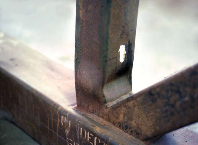
The easiest way to explain this effective width phenomenon is with a picture of a transverse plate under tension connected to the HSS chord/column face. Figure 1 is a test specimen showing the edges of the transverse plate failing from the tension while the center of the plate is still intact. Intuitively, when the load is applied to the plate, it will spread out evenly over the width of the plate. However, as shown in Figure 1, the stiffness of the HSS chord face is not uniform across the width. Think of the HSS connecting face as being “fixed” by the sidewalls at the bent corners of the HSS section. The center of the HSS flat deflects similarly to a fixed-end “beam” under a uniform load as shown in Figure 2. The deflection diagram demonstrates the variable stiffness along its length. Near the ends, the deflection is minimal because there is higher stiffness due to the fixity inherent at the HSS corner radii in contrast to the center where there is much less relative stiffness.
Image left: (a) elastic stress distribution, Image center: (b) stress distribution at failure, Image right (c) assumed effective width
Going back to the fundamentals of engineering, the load will pass through the elements in proportion to the stiffness. Thus, the highest amount of load passes through at the edges while a much smaller amount passes through in the vicinity of the chord face center. Figure 3a shows the distribution of the load for elastic behavior. Once the plate edges begin to yield locally, the stress redistributes per plastic behavior as shown in Figure 3b. An exact calculation of the stress distribution is difficult to determine. To simplify the calculation, an equivalent rectangular distribution is assumed to concentrate the load over only a portion of the plate width. This assumed effective width is split evenly on the two sides of the plate as shown in Figure 3c. Returning to Figure 1, this is the exact behavior that was observed in testing. As the tube face deflects under the load, stress concentrations form at the ends of the plate, leading to failure starting at the edges of the plate. Note that the variation in stress also occurs in compression elements, which can lead to premature failure of the branch as shown in Figure 4.
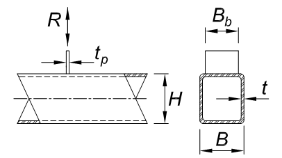
Understanding the distribution of the axial stresses from this phenomenon is essential to the next step of determining the total effective width of the plate. Through experimentation, the effective width is based on the relative stiffness of both the plate and the HSS tube connecting face. Using the lower bound test results, the effective width (Be) is determined with AISC 360-16 Equation K1-1. The ratio of the chord thickness to width (t/B) is multiplied with the ratio of yield stress multiplied by thickness (Fyt / Fybtb) between the plate (or branch) and chord. Figure 5 defines the variables with tb being equal to the thickness of the plate tp per AISC definition.

Connection Types
In addition to the transverse plate discussed above, the limit state of branch local yielding applies to any HSS connection that has a load or component of a load normal to the HSS connecting face. These connection types include T-, Y-, cross- and K-connections. Additionally, the weld connecting the plate or branch to the HSS chord is similarly affected by uneven load distribution. The effective widths of the weld at the branch walls are also derived from Equation K1-1. The weld should still be placed across the full width of the branch but, in certain cases, will only be partially effective.
Transverse Plate
For the design of the transverse plate connections, the local yielding due to uneven load distribution uses the effective width of the plate (Be), as described earlier, with Equation K1-1. To determine the axial capacity of the plate, multiply the effective plate width by the plate thickness. Second, substitute the effective area for the gross area in AISC 360-16 Equation J4-1. The capacity of the weld between transverse plate and HSS chord face will similarly be affected. Table K5.1 (AISC 360-16) allows the weld capacity to be determined using the same effective width (Be) and then doubling it since there are two total welds.
T-, Y-, and Cross-Connections
For the local yielding capacity of rectangular T-, Y- and cross-connections under axial load, each HSS branch has four walls to consider. Looking first at the two transverse walls of the branch, the main assumption is that the behavior of these walls will be the same as a pair of transverse plates. Thus, the effective width is determined exactly as described above in Equation K1-1 except that tb is now the thickness of the branch walls. Secondly, consider the two walls parallel to the chord axis. Note that they are located on the chord connecting face along a location of constant stiffness near the stiffest portion and thus are assumed to be fully effective. The length of wall to consider extends between the centerlines of the transverse walls (Hb – t), which you can see in Figure 6a. Therefore, the local yielding due to uneven load distribution calculation for the effective branch area will be the sum of the four effective widths multiplied by the HSS thickness tb. Plugging the effective area again into Equation J4-1 (AISC 360-16) will produce the branch capacity.
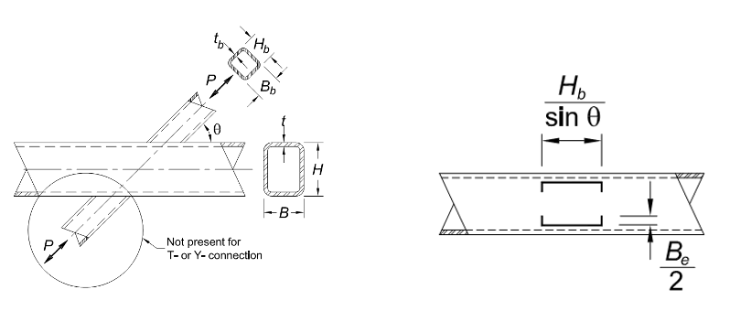
Focusing on the weld strength between branch and chord also follows a similar pattern of effective width. The main difference is that when the angle between the branch and chord is other than 90o, the length of the two walls parallel to the chord will be longer than Hb based on geometry (see Figure 6b). This means the total effective weld length will be longer than the total effective HSS wall length.
Gapped K
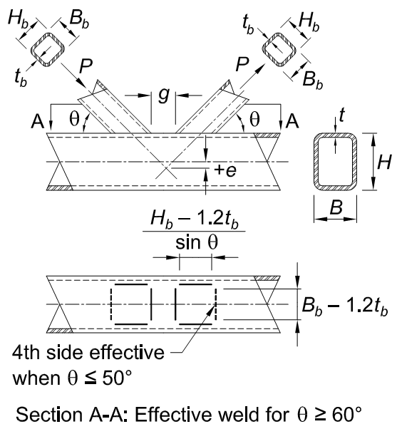
Each branch of a gapped K-connection is treated similarly to a Y-connection as described above but with a few differences. Both branches are attached to the same connecting face of the chord; however, one branch is in tension and the other is in compression. The two interior branch walls (one from each branch) nearest each other will provide some additional stiffness to the chord face due to the opposing force components. Therefore, these two HSS walls are considered fully effective. When determining the local yielding capacity, three of the four walls for each branch use the full width while the fourth (exterior) wall will use the plate effective width calculations (see Figure 7). This is all summarized in AISC 360-16 Equation K3-9.
Pn = Fybtb (2Hb + Bb + Be – 4tb)
Equation K3-9 AISC 30-16
The effective length of the weld between branch and chord in gapped K-connections depends on the angle (θ) between the two members. See AISC 360-16 Table K5.1 and Figure 7. When θ ≥ 60o, the weld on the exterior side of the branch is considered not to be effective, so only the weld on three sides of the branch is considered for strength. However, when θ ≤ 50o, the exterior weld is considered to be fully effective and all four sides are included in the weld length. Between these two angles, the exterior weld is only considered partially effective, and the total weld length is determined by interpolation between 50o and 60o.
Overlapped K
Local yielding due to uneven load distribution in K-connections that are partially or fully overlapped is handled a bit differently from the rest of the connections discussed thus far. Due to the overlap, which ties the two branch members together, the effective area of each branch is dependent on the relative stiffnesses of all three HSS members (two branches and the chord) as well as the percentage of branch overlap (see Figure 8a). The effective widths of the two exterior branch HSS walls are based on a similar methodology from the transverse plate but take into account the relative stiffnesses. However, the percentage of branch overlap affects the effective length of the HSS branch walls parallel to the chord. Additionally, when there is more than 80% overlap, one transverse wall of the overlapping ( i ) branch is considered fully effective. This can be difficult to follow, but AISC 360-16 Table K3.2 lays out a series of equations that address all of the various conditions.
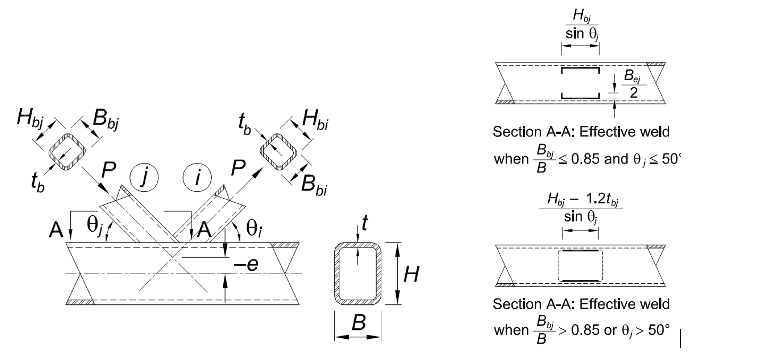
The total effective weld for overlapped K-connections is equally complicated as it is again based on both the percentage of the overlap and the connection geometry. AISC 360-16 Table K5.1 (see Figure 8b) lays out another series of equations to determine the total effective weld length. However, there are a couple geometric maximum limitations noted in the table that must be accounted for.
HSS Moment Connections
In-Plane Moment Connection
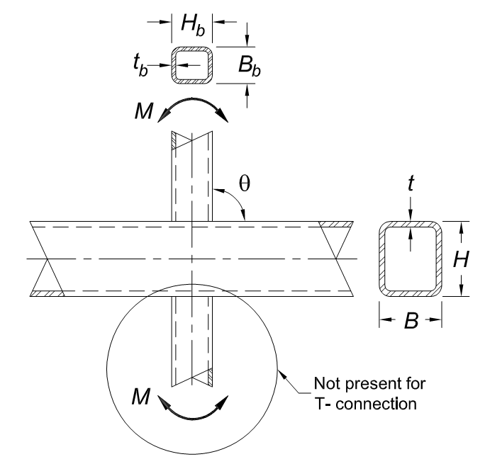
When designing HSS moment connections, there is much similarity to the axial connections covered in this article. For connections with in-plane moments (see Figure 9), one transverse branch wall is in compression while the other transverse branch wall is in tension. This returns to the transverse plate connection model. One key difference is that the branch side walls parallel to the chord experience a load gradation. A portion of the parallel wall is in tension and a separate portion is in compression; however, they are still considered fully effective.
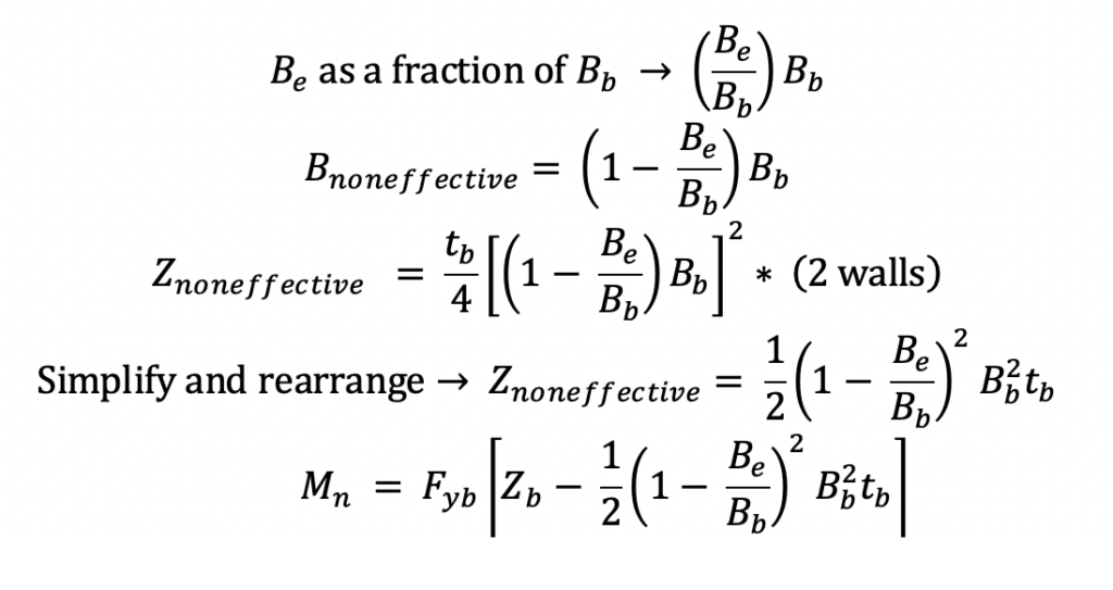
In AISC 360-16, the flexural capacity of the branch local yielding must be derived using the principles of effective width as it applies to HSS branch sections. To verify the derivation is correct, the final moment capacity equation below can be confirmed by comparing with AISC 360-10 Equation K3-8. The moment strength of the branch at the connection is determined with AISC 360-16 Equation F7-1 Mn = Mp = FyZ. However, due to the effective width phenomenon, it is known that a portion of the area is not effective, thus the plastic section modulus (Znet) should be reduced. From Figure 6b, the plastic section modulus of the noneffective areas should be subtracted from the plastic section modulus of the gross branch section (Zb). See the following derivation.
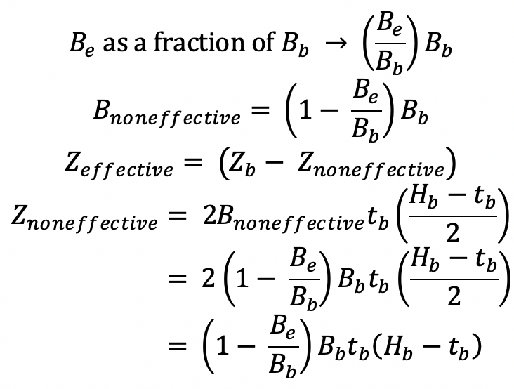
Looking closer at the term (Hb – tb), the thickness compared to wall width is a small percentage. Thus, to help simplify the equation, the tb can be ignored for a conservative result.

Following are the final steps in the derivation of the branch moment strength by filling in the value of Znet in Equation F7-1 (AISC 360-16).

Finally, for the moment strength of the effective weld group, AISC 360-16 Table K5.1 provides the section modulus properties of the effective weld group for in-plane moments for use with elastic weld design.
Out-of-Plane Moment Connection
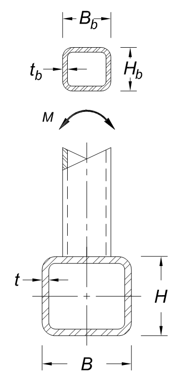
The strength of out-of-plane HSS moment connections follows the same methodology as in-plane moment connections. The only difference is that the axis of bending rotates 90o about the branch (see Figure 10). Following similar steps, the branch flexural strength must be derived in 360-16 with a verification using AISC 360-10 Equation K3-11. The weld group effective properties for out-of-plane moments are listed in AISC 360-16 Table K5.1.
Concluding Thought
Reviewing all of the information in this article should produce a better understanding of the local yielding due to the effects of uneven load distribution in HSS connections. The article discussed the impacts on the different types of HSS connections while noting that each case is simply a variation of the original transverse plate effective width calculation. There are more provisions and details for each connection type, which can be found in the AISC Specification Commentary and AISC Design Guide 24. For additional guidance on HSS connection limit states including a summary of the equation substitutions as described in this article as well as design examples, refer to the Steel Tube Institute resources available on our website, such as the STI Limit States Tables and HSS Design Manuals volumes 3 and 4.
References
AISC, 1997. “Hollow Structural Sections Connections Manual,” American Institute of Steel Construction, Chicago, IL.
AISC, 2010. “Specification for Structural Steel Buildings,” ANSI/AISC 360-10, American Institute of Steel Construction, Chicago, IL.
AISC, 2011. “Steel Construction Manual, Fourteenth Edition,” American Institute of Steel Construction, Chicago, IL.
AISC, 2016. “Specification for Structural Steel Buildings,” ANSI/AISC 360-16, and Commentary, American Institute of Steel Construction, Chicago, IL.
AISC, 2017. “Steel Construction Manual, Fifteenth Edition,” American Institute of Steel Construction, Chicago, IL.
McCormick, J. 2016. “Square and Rectangular HSS-to-HSS Moment Connections,” Steel Tube Institute, September.
Olson, K. 2020. “CJP HSS Welds: Be Informed Before You Specify,” Steel Tube Institute, May.
Packer, J.A., Wardenier, J., Zhao, X.L., van der Vegte and Kurobane, Y. 2009. “Design Guide for Rectangular Hollow Section (RHS) Joints under Predominantly Static Loading,” CIDECT Design Guide No. 3, 2nd edition, CIDECT, Geneva, Switzerland, ISBN 978-3-938817-04-9.
Packer, J., Sherman, D. and Lecce, M. 2010. “Hollow Structural Section Connections,” Steel Design Guide No. 24, American Institute of Steel Construction, Chicago, IL.
Packer, J.A. 2012. “Welding of Hollow Structural Sections,” Steel Tube Institute, March/April.
Packer, J.A. 2019. “Stepped HSS T- and Cross-Connections Under Branch In-Plane and Out-of-Plane Bending,” Steel Tube Institute, March.
STI, 2020. “Limit State Table,” Steel Tube Institute.
February 2021