Plate-Reinforced HSS Connections
By Jeffrey A. Packer
Bahen/Tanenbaum Professor of Civil Engineering, University of Toronto, Ontario, Canada
Reinforcement of HSS connections is something that can be avoided at the design stage by judicious selection of HSS members. In fact, a User Note to Section K1 of the Specification (AISC, 2016) states that … “Connection strength is often governed by the size of HSS members, especially the wall thickness of truss chords, and this must be considered in the initial design. To ensure economical and dependable connections can be designed, the connections should be considered in the design of the members.” Unfortunately, this is not always done. Sometimes, connection design is performed even after members are procured, leading to some connections requiring reinforcement. The Specification (AISC, 2016), the Manual (AISC, 2017) and AISC Design Guide No. 24 (Packer et al., 2010) do not cover reinforced HSS connections, but some advice and guidance is given elsewhere (Packer and Henderson, 1997; CEN, 2005, 2019; Wardenier et al., 2008; Packer et al., 2009). To strengthen HSS connections there are generally two options: (i) to fill the main through (chord) member with concrete or grout, or (ii) to weld on steel reinforcing plates. The first option (concrete filling) has been described in a previous STI Technical Article (Packer, 2020). This article deals with methods for HSS connection reinforcement by the addition of steel plates. Such reinforcement can enhance both the fatigue life and static strength of welded HSS connections, with the static strength considered herein.
Plate-Reinforced Round HSS Connections
Internal Ring Stiffeners
For round-to-round HSS connections, internal ring stiffeners have been widely used in offshore steel structures, yet quantitative guidance for the design of such connections is not given in any of the major offshore design codes. Qualitatively, experimental research has shown that the ultimate strength of ring-stiffened T-connections is typically around twice that of their unstiffened counterparts, when three annular rings are used and aligned with the crown and saddle positions of the branch (Ramachandra Murthy et al., 1992; Thandavamoorthy et al., 1999). Lee and Llewelyn-Parry (2004) found that the most efficient stiffening (for strength enhancement) was obtained by placing a single stiffener centrally under a branch, at the saddle position. The capacity of a T-connection with this single stiffener was shown to be given by the sum of the strengths of the unstiffened connection and of the stiffener. The unstiffened connection nominal strength can be obtained from AISC 360-16 Table K3.1 (AISC, 2016) and the stiffener nominal strength from (Lee and Llewelyn-Parry, 2004):

where Fys is the yield stress of the stiffener, ts is the thickness of the stiffener, ds is the depth of the annular stiffener (outside radius minus the inside radius), β is branch-to-chord diameter ratio, t is the chord thickness, and D is the chord diameter. Eq. (1) is empirically derived and has the validity range of: 0.1 ≤ ds /D ≤ 0.2, 0.4 ≤ ts /t ≤ 0.8, 20 ≤ 2γ = D/t ≤ 60, and 0.33 ≤ β ≤ 0.8. Using an internal ring stiffener within a large-diameter chord member of an offshore structure is a feasible proposition, especially as the connection region is often composed of a short-length chord “can” which enables access inside the chord member. For most onshore structures, internal stiffening of the chord member is impractical and external stiffening would be favored.
External Plate Stiffeners
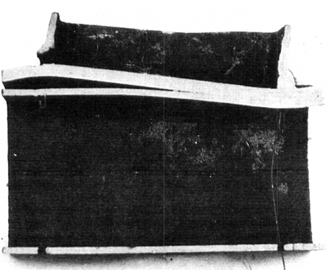
To enhance the strength of connections with thin-walled chords, reinforcement with doubler or collar plates may be used. Doubler plates are welded to the chord member, with the branch(es) welded to the doubler plate (Figure 1(a)). The doubler plate is normally welded only around its perimeter, to the chord. This is an efficient reinforcing method for branches in axial compression, where the capacities of the chord face and the doubler plate are additive. However, for branches loaded in axial tension or bending, one must be aware that the doubler plate separates from the chord face when loaded in tension (Figure 1(b)). In such cases the connection capacity can be conservatively taken as that of the doubler plate alone (and hence the doubler plate must be thicker than the chord member).
(b) welding of the collar plates to both the branch and chord members
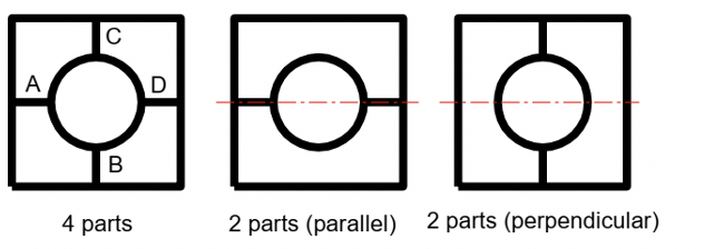
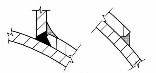
In the case of collar plates, each branch is welded to the chord member while the collar – consisting of two or four parts – is welded to both the chord and the branch, as shown in Figure 2. Collar plates generally give a greater enhancement of the connection strength than a doubler plate. For connections loaded predominantly by branch in-plane bending, collar plates with two parts parallel to the chord axis are the preferred option, whereas for connections loaded predominantly by branch out-of-plane bending the two parts perpendicular to the chord axis are preferred (see Figure 2(a)). The 4-part collar plate is recommended for branch axial tension; all options are suitable for branch axial compression.
Considerable research has been performed on plate-reinforced connections by Choo et al. (2004a, 2004b, 2005) and van der Vegte et al. (2005). As shown by their example in Figure 3, the normalized strength of a reinforced connection (vertical axis) is a function of: 2γ = D/t; β; τc = ts /t; lc /d1 = length of reinforced connection region measured in the chord axis direction, relative to the branch diameter; and the type of loading.

Plate-Reinforced Rectangular HSS Connections
The type of reinforcement required depends upon the governing failure mode (limit state) that causes the inadequate connection capacity. There are various types of plate reinforcement for rectangular HSS:
(i) Plates welded to the chord connecting face (to address chord face plastification, chord face punching shear, or local yielding of a branch due to uneven load distribution);
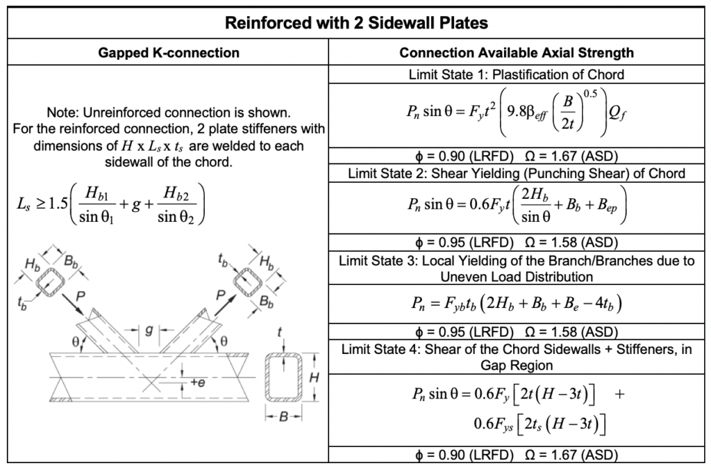
(ii) A pair of side plates welded to the chord sidewalls (to address chord sidewall yielding, chord sidewall buckling, or shearing of the chord cross section);
(iii) In order to avoid partial overlapping of branch members in a K-connection, the branch members may be welded to a single division plate (Figure 4(a)).
Combinations of these reinforcing methods may also be used; e.g., Figure 4(b). The use of a division plate (Figures 4(a) and 4(b)) is recommended over butting two double-mitered branches together (Figure 4(c)) because of the difficulty associated with proper welding of the branch webs to each other.

Reinforced T-, Y- and Cross-Connections
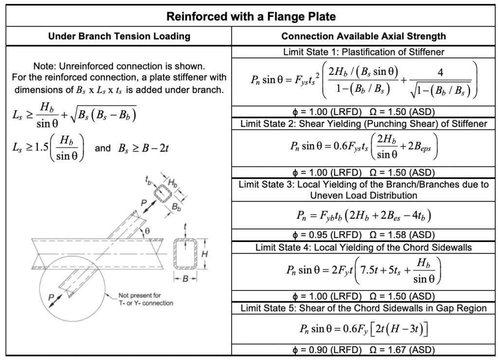
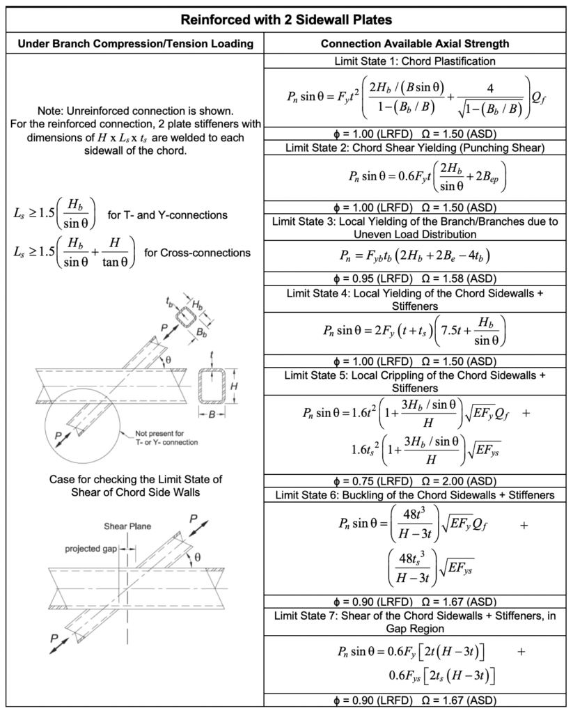
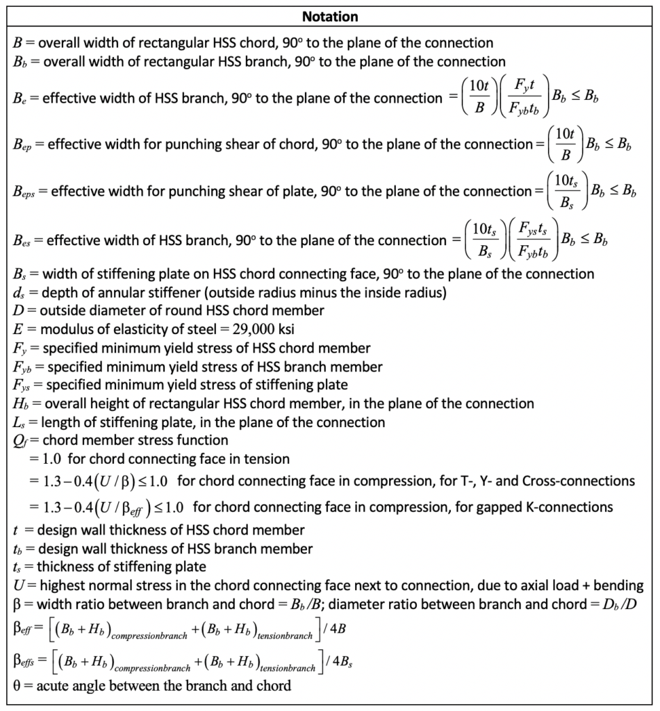
Design recommendations from Eurocode 3 (CEN, 2019), adapted to AISC 360-16 for the possible limit states, are given in Tables 1, 2 and 3. A list of Notation (definition of symbols) follows the tables. The grade of steel used for the reinforcement should not be lower than that of the chord member.
For T-, Y- and Cross-connections reinforced with a flange plate, there is a difference in behavior of the stiffening plate depending on the sense of the load in the branch member. With a tension load in the branch, the plate tends to lift off the chord member (see Figure 1(b)) and behave as a plate clamped (welded) along its four edges. The strength of the connection depends primarily on the plate geometry and properties, instead of the chord connecting face, which is reflected in Table 1. With a compression load in the branch, Korol et al. (1982) have shown that the plate and the chord connecting face can be expected to both contribute to the connection resistance, so for the limit states of chord plastification and chord punching shear the chord-face contribution and the flange-plate contribution are added, assuming unconnected elements (see Table 2).
Table 1: Available strengths for welded, flange-plate-reinforced, rectangular HSS T-, Y- and Cross-connections under branch tension
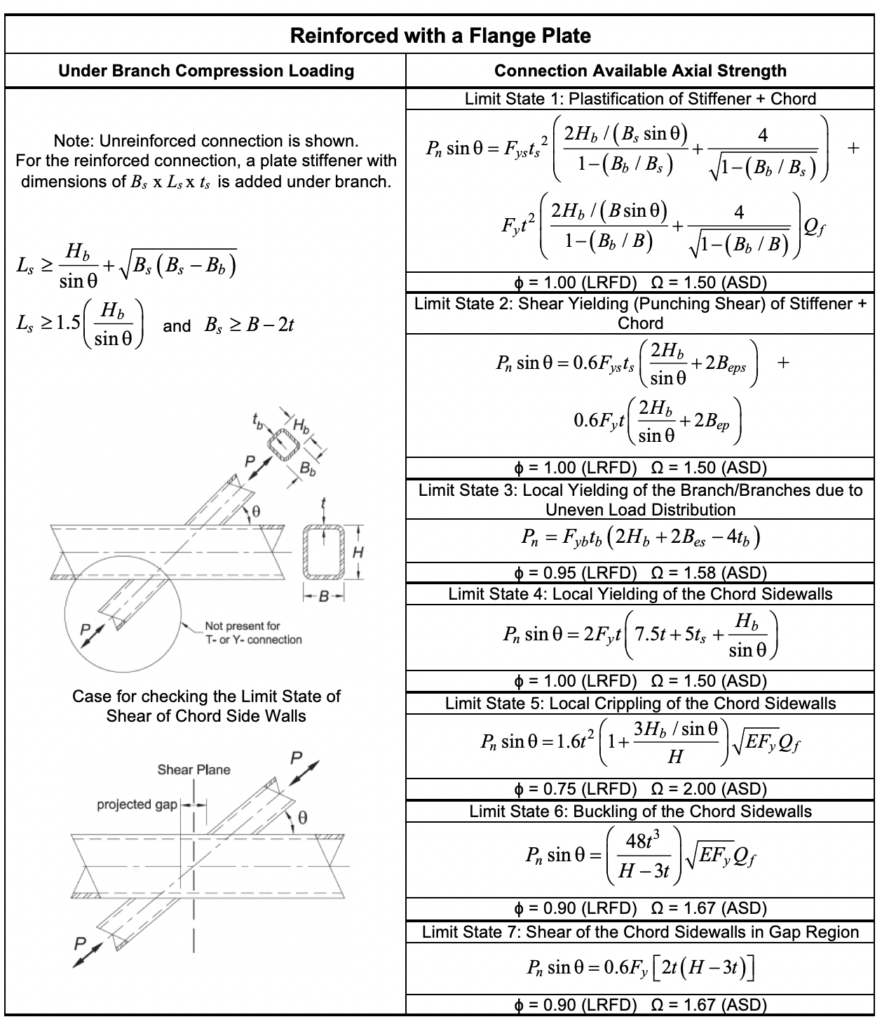
Table 2: Available strengths for welded, flange-plate-reinforced, rectangular HSS T-, Y- and Cross-connections under branch compression
For T-, Y- and Cross-connections reinforced with a pair of plates to the outside of the two sidewalls of the chord, design recommendations are given in Table 3. In this table, limit state expressions pertaining to chord sidewall failure are adjusted to take account of the contribution of the reinforcing plates (CEN, 2019).
Table 3: Available strengths for welded, sidewall-reinforced, rectangular HSS T-, Y- and Cross-connections
Reinforced K-Connections
Design recommendations from Eurocode 3 (CEN, 2019), adapted to AISC 360-16 for the possible limit states, are given in Tables 4, 5 and 6, for various types of reinforcement. As noted before, a list of Notation (definition of symbols) follows the tables. The grade of steel used for the reinforcement should not be lower than that of the chord member.
Table 4: Available strengths for welded, flange-plate-reinforced, rectangular HSS gapped K-connections
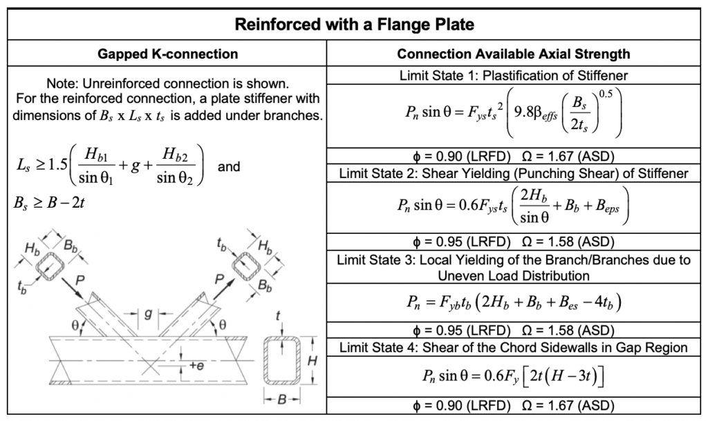
Table 5: Available strength for welded, division-plate-reinforced rectangular HSS overlapped K-connections (see Figure 4(a))
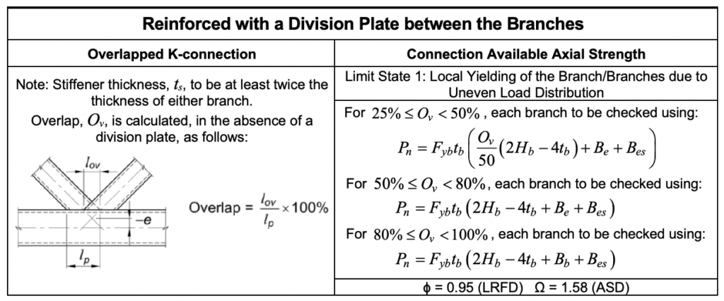
Table 6: Available strengths for welded, sidewall-reinforced, rectangular HSS gapped K-connections
References
AISC. 2016. “Specification for Structural Steel Buildings”, ANSI/AISC 360-16, American Institute of Steel Construction, Chicago, IL.
AISC. 2017. “Steel Construction Manual”, 15th. edition, American Institute of Steel Construction, Chicago, IL.
CEN. 2005. “Eurocode 3 – Design of Steel Structures – Part 1-8: Design of Joints”, EN 1993-1-8: 2005, European Committee for Standardization, Brussels, Belgium.
CEN. 2019. “Eurocode 3 – Design of Steel Structures – Part 1-8: Design of Joints”, prEN 1993-1-8, European Committee for Standardization, Brussels, Belgium.
Choo, Y.S., Liang, J.X., Vegte, G.J. van der and Liew, J.Y.R. 2004a. “Static Strength of Doubler Plate Reinforced CHS X-Joints Loaded by In-Plane Bending”, Journal of Constructional Steel Research, Vol. 60, pp. 1725-1744.
Choo, Y.S., Liang, J.X., Vegte, G.J. van der and Liew, J.Y.R. 2004b. “Static Strength of Collar Plate Reinforced CHS X-Joints Loaded by In-Plane Bending”, Journal of Constructional Steel Research, Vol. 60, pp. 1745-1760.
Choo, Y.S., Vegte, G.J. van der, Zettlemoyer, N., Li, B.H. and Liew, J.Y.R. 2005. “Static Strength of T-Joints Reinforced with Doubler or Collar Plates. I: Experimental Investigations”, ASCE Journal of Structural Engineering, Vol. 131, No. 1, pp. 119-128.
Korol, R.M., Mitri, H. and Mirza, F.A. 1982. “Plate Reinforced Square Hollow Section T-Joints of Unequal Width”, Canadian Journal of Civil Engineering, Vol. 9, No. 2, pp. 143-148.
Lee, M.M.K. and Llewelyn-Parry, A. 2004. “Offshore Tubular T-Joints Reinforced with Internal Plain Annular Ring Stiffeners”, ASCE Journal of Structural Engineering, Vol. 130, No. 6, pp. 942-951.
Packer, J.A. 2020. “Concrete-Filled HSS Connections”, Steel Tube Institute Technical Article, https://steeltubeinstitute.org/resources/concrete-filled-hss-connections/
Packer, J.A. and Henderson, J.E. 1997. “Hollow Structural Section Connections and Trusses – A Design Guide”, 2nd. edition, Canadian Institute of Steel Construction, Toronto, ON.
Packer, J.A., Sherman, D.R. and Lecce, M. 2010. “Hollow Structural Section Connections”, Steel Design Guide No. 24, 1st. edition, American Institute of Steel Construction, Chicago, IL.
Packer, J.A., Wardenier, J., Zhao, X.-L., van der Vegte, G.J. and Kurobane, Y. 2009. “Design Guide for Rectangular Hollow Section (RHS) Joints under Predominantly Static Loading”, CIDECT Design Guide No. 3, 2nd. edition, CIDECT, Geneva, Switzerland.
Ramachandra Murthy, D.S., Madhava Rao, A.G., Gandhi, P. and Pant, P.K. 1992. “Structural Efficiency of Internally Ring-Stiffened Steel Tubular Joints”, ASCE Journal of Structural Engineering, Vol. 118, No. 11, pp. 3016-3035.
Thandavamoorthy, T.S., Madhava Rao, A.G. and Santhakumar, A.R. 1999. “Behavior of Internally Ring-Stiffened Joints of Offshore Platforms”, ASCE Journal of Structural Engineering, Vol. 125, No. 11, pp. 1348-1352.
Vegte, G.J. van der, Choo, Y.S., Liang, J.X., Zettlemoyer, N. and Liew, J.Y.R. 2005. “Static Strength of T-Joints Reinforced with Doubler or Collar Plates. II: Numerical Simulations”, ASCE Journal of Structural Engineering, Vol. 131, No. 1, pp. 129-138.
Wardenier, J., Kurobane, Y., Packer, J.A., van der Vegte, G.J. and Zhao, X.-L. 2008. “Design Guide for Circular Hollow Section (CHS) Joints under Predominantly Static Loading”, CIDECT Design Guide No. 1, 2nd. edition, CIDECT, Geneva, Switzerland.
March 2021