Concrete-Filled HSS Connections
By Jeffrey A. Packer
Bahen/Tanenbaum Professor of Civil Engineering, University of Toronto, Ontario, Canada
Pros and Cons of Concrete Filling
Ever since the arrival of hollow sections, there has been an interest in filling the HSS void. All too often, the decision to fill, or partially fill, a hollow section is taken at a late stage of the design or fabrication in order to resolve a problem (e.g., to meet fire resistance requirements or to strengthen a critical part of the structure). Consideration of concrete filling HSS early in the design process will enable the typical benefits to be fully utilized. In relation to unfilled HSS, concrete-filled HSS offer a number of advantages (BSC, 1984; Wardenier et al., 2010; Zhao et al., 2019):
- An increase in the load-bearing capacity, in both compression and flexure. This is covered in Chapter I of AISC 360 (AISC, 2016). Although several design methods are presented there for composite members, the relatively simple “plastic stress distribution method” is applicable to nearly all composite round and square HSS manufactured to ASTM A500 Grade C (ASTM, 2018) and ASTM A1085 (ASTM, 2015). All but five HSS are classified as “compact” in axial compression, and all but 11 HSS are classified as “compact” in flexure. Composite round HSS have an advantage over composite square HSS with the same steel area because the former are permitted a higher design stress for the concrete to reflect the effect of concrete confinement.
- A reduction in the quantity of steel required, hence a lighter HSS, for the same applied load.
- A smaller diameter or outside dimension, for the same applied load, resulting in a reduction of the floor space occupied by a column, as well as a lower surface area for coatings.
- An increase in the fire resistance (either with or without external protection), and especially with the addition of longitudinal steel reinforcing bars (rebars) or steel fibers to the concrete.
- An increase in the stiffness of columns in building frames. An effective flexural stiffness, EIeff, is used for composite columns, utilizing the flexural stiffnesses of the HSS, rebars and concrete.
- A potential increase in the strength of connections (which is the topic of this article).
Relative to reinforced concrete columns, concrete-filled HSS also present advantages: the elimination of formwork; an appreciable decrease in the occupied floor space; the omission, in many cases, of rebars; the introduction of off-site fabrication, and faster on-site construction; and the introduction of tighter construction tolerances, typical of steel construction.
Relative to unfilled HSS, concrete-filled HSS have the disadvantage of coordinating two different trades and the associated cost that filling may entail. However, this should not be a barrier in an age when innovation is needed in the construction industry. Although concern has sometimes been raised about the mechanical bond between HSS and concrete, this has been shown to be a non-issue (and hence mechanical shear connectors are not required for full composite action) for manufactured HSS sizes (Lu and Kennedy, 1994). A non-shrink concrete/grout fill should also be specified.
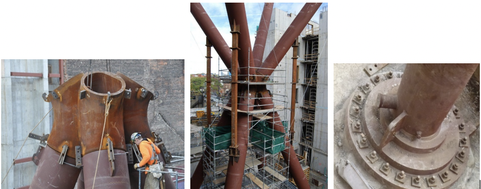
Figure 1 illustrates a recent application of concrete filling round HSS members, with pumped concrete introduced through a spigot at the bottom of each tube.
Concrete-Filled Connections
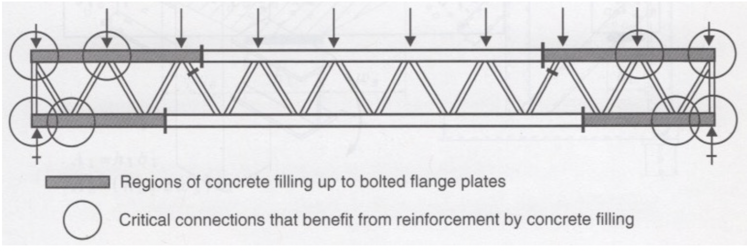
Concrete filling of the main “through” member in truss-type connections has been advocated as a means of connection reinforcement. With short-span trusses, all of the chord member could be filled; with long-span trusses — which can be assembled with bolted flange plates in the chord to facilitate transportation and erection — only a part of the chord needs to be filled with concrete or grout, as shown in Figure 2 (Packer and Henderson, 1997).
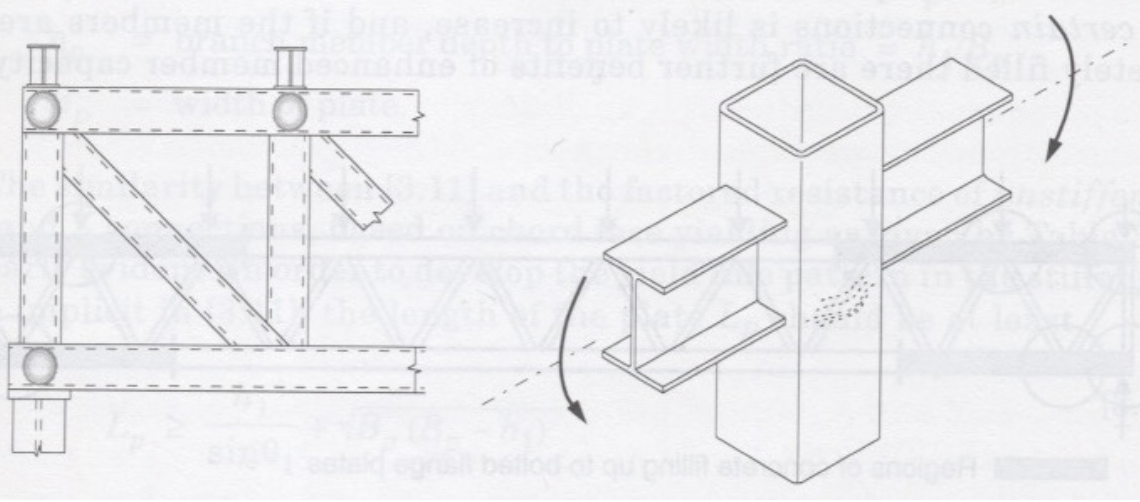
Although not covered in AISC Design Guide No. 24 (Packer et al., 2010), design guidance for concrete-filled HSS connections has been offered elsewhere (Packer and Henderson, 1997; Packer et al., 2009; Zhao et al., 2010). Experimental research (Packer, 1995; Li and Young, 2018) has shown that concrete filling particularly enhances the performance of hollow sections under transverse compression. The hollow section provides containment for the concrete, which allows it to reach bearing capacities somewhat greater than its crushing strength defined by cylinder compression tests, fc/. Examples of connections at which a compression force is transferred through the HSS, and hence that are likely to particularly benefit from concrete filling, include: truss reaction points, truss connections at which there is a significant external load, and beam-to-column moment connections, as illustrated in Figure 3.
Rectangular HSS Cross Connections With Branches in Compression
The LRFD available strength, φcPn, for the limit state of concrete failure in compression, can be determined from the nominal strength, Pn (Packer et al., 2009):
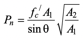
where fc/ is the specified compressive strength of the concrete, θ is the acute angle between the HSS or plate branch and the chord member, A1 is the bearing area over which the transverse load is applied (e.g., Hb Bb for an HSS branch at 90o), and A2 is the dispersed bearing area. A2 should be determined to be dispersion of the bearing load at a slope of 2:1, just longitudinally, along the chord member to the chord mid-depth. Thus, for symmetrical dispersion in both directions:
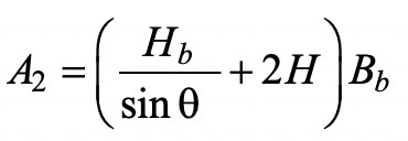
where, for an HSS branch, Hb is the branch overall height measured in the plane of the connection, and Bb is the branch overall width measured 90o to the plane of the connection; H is the chord overall height measured in the plane of the connection. In Eq. (1), cannot be taken to have a value greater than 3.3, in calculations. The value A2 may be limited by the length of the concrete fill, Lc. Ideally, Lc, measured symmetrically about the loaded bearing area, should be greater than the dispersion length, Ac; i.e., Lc > (Hb / sin θ + 2H). This design procedure was validated by experiments on concrete-filled HSS with an aspect ratio of H/B ≤ 1.4 (Packer, 1995), where B is the chord overall width measured at 90o to the plane of the connection. To obtain the LRFD available strength from Eq. (1), a resistance factor of φc = 0.65 is recommended (Packer et al., 2009), which is almost identical to what one might compute from AISC 360 Chapter I for composite members (AISC, 2016), using 0.75(0.85).
Rectangular HSS T- and Y-Connections With Branches in Compression
Since the load in this case is being resisted by shear forces in the chord, rather than being transferred through the chord, the dispersed bearing area A2 should be calculated assuming a stress distribution longitudinally at a slope of 2:1 through the entire depth of the chord, rather than to an (A2/A1) limit. Thus, the nominal strength can be obtained again from Eq. (1), but Eq. (2) can be adjusted to:
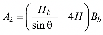
Similarly, the ideal length of the concrete fill can be adjusted to Lc > (Hb / sin θ + 4H).
Rectangular HSS T- and Y- and Cross Connections With Branches in Tension
In tests, none of the concrete-filled connections with branches in tension exhibited a decrease in the connection yield or ultimate strength, relative to their unfilled counterparts, by more than a few percent. Connection ductility also did not appear to be compromised by concrete filling the chord. It is therefore recommended that the design of these concrete-filled connections be based upon design rules for unfilled HSS connections. [See AISC 360-16 Chapters J and K (AISC, 2016), the AISC Manual Part 9 (AISC, 2017) and AISC DG24 (Packer et al., 2010)].
Rectangular HSS Gapped K-Connections
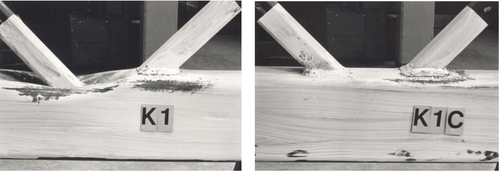
For the range of connection parameters studied experimentally (Packer, 1995), gapped K-connections with concrete-filled chords were found to have superior connection yield strengths and ultimate strengths relative to their unfilled counterparts. Also, concrete filling such connections was found to generally produce a significant change in connection failure mode, as illustrated in Figure 4. In that figure, one can see that the “push-pull action” of the compression and tension branches in an unfilled, gapped K-connection (K1) is prevented with concrete filling (K1C). Thus, the classic chord plastification limit state is prevented and the two branches act separately. It is therefore recommended that the connection resistance be calculated separately for the compression web member and the tension web member. It was also found (Packer, 1995) that the capacity of a gapped K-connection with concrete in the chord is unaffected by a moderate amount of shrinkage of the concrete away from the chord walls, thus making this technique for connection stiffening an easy option for fabricators.
For the compression web member, which presses on a relatively rigid foundation of concrete, the connection strength is limited by bearing failure of the concrete. Hence, calculations should be performed as for a compression-loaded Y-connection, using Eqs. (1) and (3).
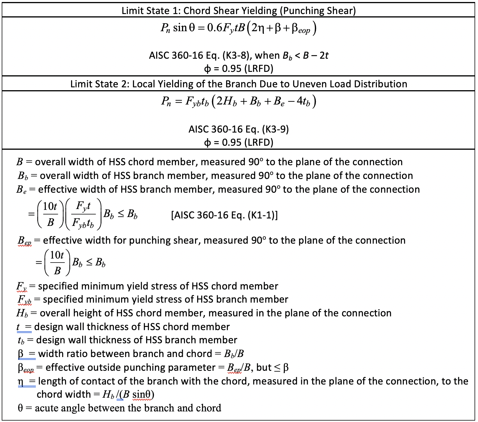
For the tension web member, the concrete filling only permits two possible failure modes: (i) chord shear yielding (punching shear) around the branch, and (ii) local yielding of the branch due to uneven load distribution. These two failure modes are a subset of the possible limit states experienced with unfilled, gapped K-connections (see AISC 360-16 Table K3.2), and the connection available strengths for these two limit states are given in Table 1.
References
AISC. 2016. “Specification for Structural Steel Buildings,” ANSI/AISC 360-16, American Institute of Steel Construction, Chicago, IL.
AISC. 2017. “Steel Construction Manual,” 15th edition, American Institute of Steel Construction, Chicago, IL, ISBN 1-56424-007-1.
ASTM. 2015. “Standard Specification for Cold-Formed Welded Carbon Steel Hollow Structural Sections (HSS),” ASTM A1085/A1085M-15, American Society for Testing and Materials International, West Conshohocken, PA.
ASTM. 2018. “Standard Specification for Cold-Formed Welded and Seamless Carbon Steel Structural Tubing in Rounds and Shapes,” ASTM A500/A500M-18, American Society for Testing and Materials International, West Conshohocken, PA.
BSC. 1984. “Construction with Hollow Steel Sections,” British Steel Corporation Tubes Division, Corby, UK.
Li, H.T. and Young, B. 2018. “Experimental Investigation of Concrete-Filled High-Strength Steel Tubular X Joints,” ASCE Journal of Structural Engineering, Vol. 144, No. 10, pp. 04018178:1-13.
Lu, Y.Q. and Kennedy, D.J.L. 1994. “The Flexural Behaviour of Concrete-Filled Hollow Structural Sections,” Canadian Journal of Civil Engineering, Vol. 21, pp. 111-130.
Packer, J.A. 1995. “Concrete-Filled HSS Connections,” ASCE Journal of Structural Engineering, Vol. 121, No. 3, pp. 458-467.
Packer, J.A. and Henderson, J.E. 1997. “Hollow Structural Section Connections and Trusses – A Design Guide,” 2nd edition, Canadian Institute of Steel Construction, Toronto, ON, ISBN 0-88811-086-3.
Packer, J.A., Sherman, D. and Lecce, M. 2010. “Hollow Structural Section Connections,” Steel Design Guide No. 24, 1st edition, American Institute of Steel Construction, Chicago, IL.
Packer, J.A., Wardenier, J., Zhao, X.L., van der Vegte, G.J. and Kurobane, Y. 2009. “Design Guide for Rectangular Hollow Section (RHS) Joints under Predominantly Static Loading,” CIDECT Design Guide No. 3, 2nd edition, CIDECT, Geneva, Switzerland, ISBN 978-3-938817-04-9.
Wardenier, J., Packer, J.A., Zhao, X.L. and van der Vegte, G.J. 2010. “Hollow Sections in Structural Applications,” 2nd edition, CIDECT, Geneva, Switzerland, ISBN 978-90-72830-86-9.
Zhao, X.L., Han, L.H. and Lu, H. 2010. “Concrete-Filled Tubular Members and Connections,” Taylor & Francis, London, UK, ISBN 978-0-4290-8304-4.
Zhao, X.L., Packer, J.A., Wang, Y.C. and McCormick, J.P. 2019. “Design Guide for Concrete-Filled Hollow Section Columns under Static, Impact, Blast, Seismic and Fire Loading,” CIDECT Design Guide No. 10, CIDECT, Geneva, Switzerland, ISBN 978-0-7727-7552-8.
June 2020