Multi-planar Welded Connections
By Jeffrey A. Packer
Bahen/Tanenbaum Professor of Civil Engineering, University of Toronto, Ontario, Canada
AISC 360-16 Specification Section K1 starts by noting its scope: “For the purposes of this chapter, the centerlines of branch members shall lie in a common plane” (AISC, 2016). In practice, however, a great number of hollow section structures have not just planar welded connections but multi-planar connections. These may arise in towers, offshore structures, crane gantries, bridges, canopies, atria, lattice columns and roof structures. Free-form architecture has liberated and encouraged artistic expression, to the extent that designers now feel that almost any three-dimensional arrangement of members can be specified – and built. This may lead to considerable fabrication challenges such as the example in Figure 1.

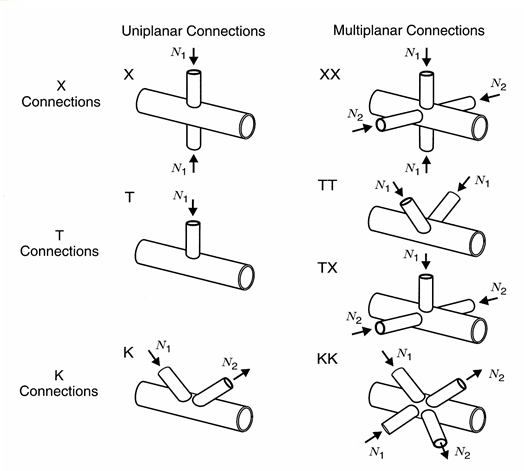
Most space frames are designed as pin-connected systems, which results in member axial forces only, thus the design of many multi-planar welded connections (to a main or “through” member) can be related to their axially loaded planar connection counterparts. Terminology for multi-planar connections has been adopted such that if a second plane at a node contains a second X- (or Cross-), T- or K-connection, then the connection is termed an XX-, TT- or KK-connection, respectively. Similarly, a T-branch in a plane orthogonal to a planar X-connection would produce a multi-planar TX-connection (or alternatively it could be viewed as an XT-connection), and so forth. However, such truss-type connection labels are still subject to the connection classification rules based on force transfer, as described in the AISC 360-16 Commentary Section K1 and in AISC Design Guide No. 24 (Packer et al., 2010). Several basic multi-planar connection types, relative to their uni-planar counterparts, are shown in Figure 2.

AWS (2015) provides a means of handling multi-planar effects for round HSS connections, but the design rules are relatively complex and, depending on the configuration and loading of the connections, they may be unreliable for strength predictions. A great number of researchers, as summarized by Packer and Henderson (1997), Wardenier et al. (2008) and Packer et al. (2009), has performed experimental and numerical studies on multi-planar, welded, HSS connections. Research increasingly identified that the “multi-planar effect” is caused by both loading and geometric effects, the latter being a function especially of the width ratio (β) and the chord wall slenderness (2γ), as for planar connections. The mere addition of more branches to a connection (i.e., welding on more steel) often serves to stiffen the connection region and provide an increase in strength.
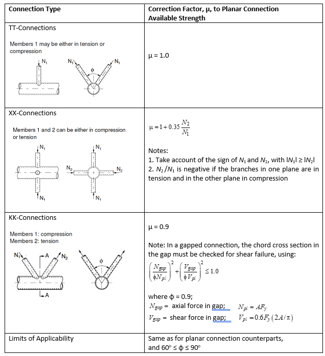
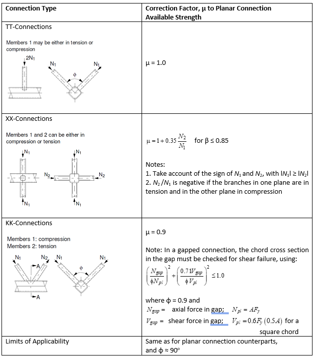
The recommended approach by CIDECT (Wardenier et al., 2008; Packer et al., 2009) for designing multi-planar connections is to consider a connection type in a single plane, and then adjust the planar connection strength (based on the controlling limit state) for the effect of the branches lying out of that plane, by a correction factor, µ. Considering the beneficial effect of welded-on branches, and ignoring the loading effect, this factor µ can be taken as 0.9 or 1.0 in many cases. This has the condition that the total chord force is used to calculate the planar connection Qf value; using either the total “prestress” for round HSS chords, or the total “maximum stress” for rectangular HSS chords. The correction factors to planar connection strength (determined from Chapters J and K of the AISC 360-16 Specification, or AISC Design Guide No. 24) are summarized, for common connection types, in Table 1 for round HSS and Table 2 for rectangular HSS. Particular remarks with regard to XX-connections and KK-connections follow.


XX-Connection Design
With a planar X- (or Cross-) connection, as shown in Figure 2 under equal and opposite branch compression forces, the round HSS chord flattens into an oval shape. For a rectangular HSS, the loaded chord faces bend inwards and the two unloaded web walls curve outwards, while the corners tend to approximately maintain their 90° angles. Thus, for both shapes the chord sides bulge outwards. If compression-loaded, out-of-plane branches are now added (as in the XX-connection of Figure 2), one can see that such forces tend to restore the chord section to its original shape and thus have a positive effect in opposing chord deformation. Conversely, tension-loaded out-of-plane branches would have the opposite effect, and would exacerbate the connection deformation. Thus, in Tables 1 and 2 the planar strength correction factor, µ, is highly dependent upon the relative sense of the forces in the pairs of X-branches. The XX-connection, with orthogonal planes of X-branches loaded in the opposite sense, is the one multi-planar connection case that can produce a severe reduction (up to 35%) relative to its uni-planar counterpart.
KK-Connection Design
For round HSS KK-connections, a simple reduction factor of µ = 0.9 can be applied to account for multi-planar effects, as indicated in Table 1. This follows CIDECT Design Guide No.1, 1st. ed. (Wardenier et al., 1991) because this particular CIDECT guide – like the AISC 360-16 Specification – is based on chord “prestress” (the lower chord stress) for calculating the round HSS Qf factor. (This can be seen in the Functions part of the AISC Specification Table K3.1). Also, the two recommendations (CIDECT Design Guide No.1 1st. ed. and the AISC 360-16 Specification) have common limit state checks for gapped and overlapped K-connections.
For rectangular HSS KK-connections, a simple reduction factor of µ = 0.9 can also be applied to account for multi-planar effects, as indicated in Table 2. This follows CIDECT Design Guide No.3, 1st. ed. (Packer et al., 1992) because this particular CIDECT guide – like the AISC 360-16 Specification – is based on chord “maximum stress” for calculating the rectangular HSS Qf factor and both recommendations have common limit state checks for gapped and overlapped K-connections.
The force in a single chord member can be considerably higher in a KK-connection than in a K-connection, because of the force components parallel to the chord from branches in two planes. Similarly, the force components normal to the chord from branches in two planes can be considerably higher in a KK-connection than in a K-connection. Thus, for gapped KK-connections, it is recommended that a free-body diagram be produced showing the chord forces acting on a section taken through the gap region, and then an interaction check be made for failure in the gap region under combined normal and shear stress. This is shown in Table 1 for round HSS and Table 2 for rectangular HSS. For round HSS KK-connections, the total “vertical” shear force in the gap (Vgap) is applied to the circular cross section where the chord shear area is taken to be (2/π)A (Wardenier et al., 2010). For the rectangular HSS gapped KK-connection, with an angle of φ = 90° between the branch planes, the connection is subjected to a shear force of (0.5√2)Vgap in each plane. The shear force in each plane is resisted by the two walls of the rectangular HSS chord. The “horizontal” components from the two planes equilibrate. For both round and rectangular HSS the shear yield stress is taken as 0.6Fy to conform to the AISC 360-16 Specification.
Fabrication Aspects with KK-Connections
Round HSS
A common initial layout for 3D modeling is to have a single work point for multiple branches on the chord centerline, but designers should be aware that this may involve more complicated fabrication procedures. In a single plane, two branch members in a K-connection may overlap each other, but in a KK-connection branch members from one plane may also overlap those from another plane. An increasing number of overlapping branches leads to more branch-end profiling, more complex fit-up, and more welding issues. To avoid overlapping branch members from one side plane onto those of the other, it may be necessary to introduce a “transverse gap” between neighboring planes, but this may introduce a work-point offset perpendicular to the chord axis. This noding eccentricity should be ≤ 0.25D in order for the bending moment generated to be ignored in terms of its primary effect on connection design. The eccentricity moment has some influence on the connection strength in that it affects the value of Qf, the chord stress influence factor. The eccentricity moment will always influence the design of the chord members, because they will need to be designed for combined axial force and flexure.
In a KK-connection, if the two compression web members overlap each other and the two tension web members overlap each other, but there is still a gap, g, along the chord between the compression and tension web members (under symmetrical loading), then the combined two-branch “footprint” can be treated as one unit with the KK-connection analyzed as a K-connection.
Rectangular HSS

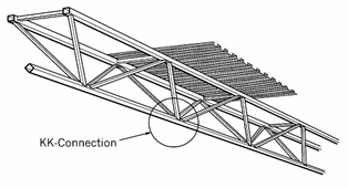
Triangular or “Delta” (Δ) trusses are frequently arranged in the form of a “V” that combines one bottom chord with two top chords, as illustrated in Figure 3. Under gravity loading this has the advantage of increased lateral stability offered by the twin, separated, but connected compression chords. These trusses are frequently used as exposed structures and are considered equivalent in appearance, but less expensive, than space frames. Square HSS chords have been used with web members framing into the corners of the chord section, by shaping the web member ends to form so-called “bird beak” connections (e.g. Minneapolis Convention Center roof, Minneapolis/St. Paul Twin Cities Airport skyway). However, it is less expensive to rotate the bottom chord by 45° and to bevel cut the web ends so that they land on the flat chord faces (as shown for KK-connections in Table 2). When serving as a roof truss, purlins may not be necessary, because the top chords can be spaced at a suitable distance apart for the roof deck to span between. The decking can then be fastened directly to the flat surfaces of the HSS top chord members.
References
AISC. 2016. “Specification for structural steel buildings”, ANSI/AISC 360-16, and Commentary, American Institute of Steel Construction, Chicago, IL.
AWS. 2015. “Structural welding code – Steel”, ANSI/AWS D1.1/D1.1M:2015, 23rd. ed., American Welding Society, Miami, FL.
Packer, J.A. and Henderson, J.E. 1997. “Hollow structural section connections and trusses – A design guide”, 2nd. ed., Canadian Institute of Steel Construction, Toronto, Canada.
Packer, J.A., Sherman, D. and Lecce, M. 2010. “Hollow structural section connections”, AISC Design Guide No. 24, 1st. ed., American Institute of Steel Construction, Chicago, IL.
Packer, J.A., Wardenier, J., Kurobane, Y., Dutta, D. and Yeomans, N. 1992. “Design guide for rectangular hollow section (RHS) joints under predominantly static loading”, CIDECT Design Guide No. 3, 1st. ed., CIDECT (Ed.) and Verlag TÜV Rheinland, Köln, Germany.
Packer, J.A., Wardenier, J., Zhao, X.L., van der Vegte, G.J. and Kurobane, Y. 2009. “Design guide for rectangular hollow section (RHS) joints under predominantly static loading”, CIDECT Design Guide No. 3, 2nd. ed., CIDECT, Geneva, Switzerland.
Wardenier, J., Kurobane, Y., Packer, J.A., Dutta, D. and Yeomans, N. 1991. “Design guide for circular hollow section (CHS) joints under predominantly static loading”, CIDECT Design Guide No. 1, 1st. ed., CIDECT (Ed.) and Verlag TÜV Rheinland, Köln, Germany.
Wardenier, J., Kurobane, Y., Packer, J.A., van der Vegte, G.J. and Zhao, X.-L. 2008. “Design guide for circular hollow section (CHS) joints under predominantly static loading”, CIDECT Design Guide No. 1, 2nd. ed., CIDECT, Geneva, Switzerland.
Wardenier, J., Packer, J.A., Zhao, X.-L. and van der Vegte, G.J. 2010. “Hollow sections in structural applications”, 2nd. ed., CIDECT, Geneva, Switzerland
June 2018