HSS Seam Welds
by Jeffrey A. Packer1
1Bahen/Tanenbaum Professor of Civil Engineering, University of Toronto, Ontario, Canada
There are two principal manufacturing methods internationally for cold-forming square and rectangular HSS: direct-forming and continuous-forming. The direct-forming process includes: (1) roll-forming a coil strip directly into an open section with the desired rectangular shape; and (2) joining the edges of the open section by welding to form a closed rectangular shape. The cold-working in this case is concentrated at the four corners. The continuous-forming process includes: (1) roll-forming a coil strip first into a circular open tube; (2) joining the edges of the open tube by welding to form a closed circular shape; and (3) flattening the circular tube to form the desired rectangular shape. Both production methods are used in North America, although the latter (continuous-forming) is much more common. The static properties of these two HSS products have been compared by Sun and Packer (2014). Both methods of HSS manufacture involve forming a closed section by continuous “welding”, using an induction heating process, without the use of any additional weld consumable.
Weld Flash
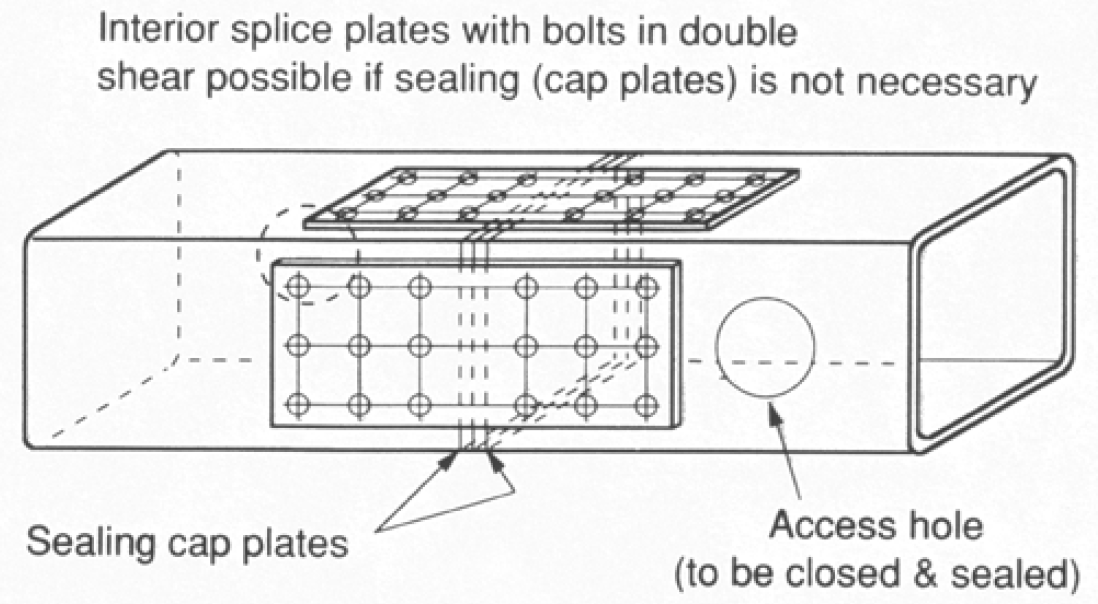
The “flash” (protruding weld metal) of the longitudinal seam weld is always removed, during the manufacturing process, on the outside of HSS, thus making the exterior of the HSS surface smooth and flush. However, welded tubing is normally furnished without removal of the inside flash, as noted by both A500 (ASTM, 2013a) and A1085 (ASTM, 2013b). Some manufacturers are able to provide HSS with inside flash removal, but this needs to be requested and confirmed prior to production. Inside flash removal is most commonly stipulated for round HSS where one tube must fit snugly inside another (e.g. telescoping applications). Sometimes the protruding inside weld flash may complicate the execution of a particular bolted connection, such as a splice connection using interior splice plates where the intention is to place the bolts in double shear (see Figure 1). This potential problem (where a splice plate cannot lie flat on the inside HSS surface due to a raised weld) can be overcome by the fabricator paying attention to the seam weld location and avoiding bolting to that wall, if not all four faces are to be connected. If all HSS faces are to be connected then shims, either side of the seam weld, could be employed.

Weld in Corner Regions
It has been generally accepted by HSS manufacturers that longitudinal seam welds should not lie in the corner regions of square and rectangular HSS. There is essentially a lack of evidence and testing to support corner seam welds, in general structural applications. Although corner seams were not mentioned in ASTM A500-10, in ASTM A500-13 Clause 6.3 was added to specifically stipulate that … “The weld shall not be located within the radius of the corners of any shaped tube unless specified by the purchaser”. In ASTM A1085-13, however, this prohibition of the seam weld in the corner is not included – yet. Thus, a weld seam located beyond the tangent point of an HSS “flat” is cause for rejection of ASTM A500 material, but not ASTM A1085 material.
Through-Thickness Welding

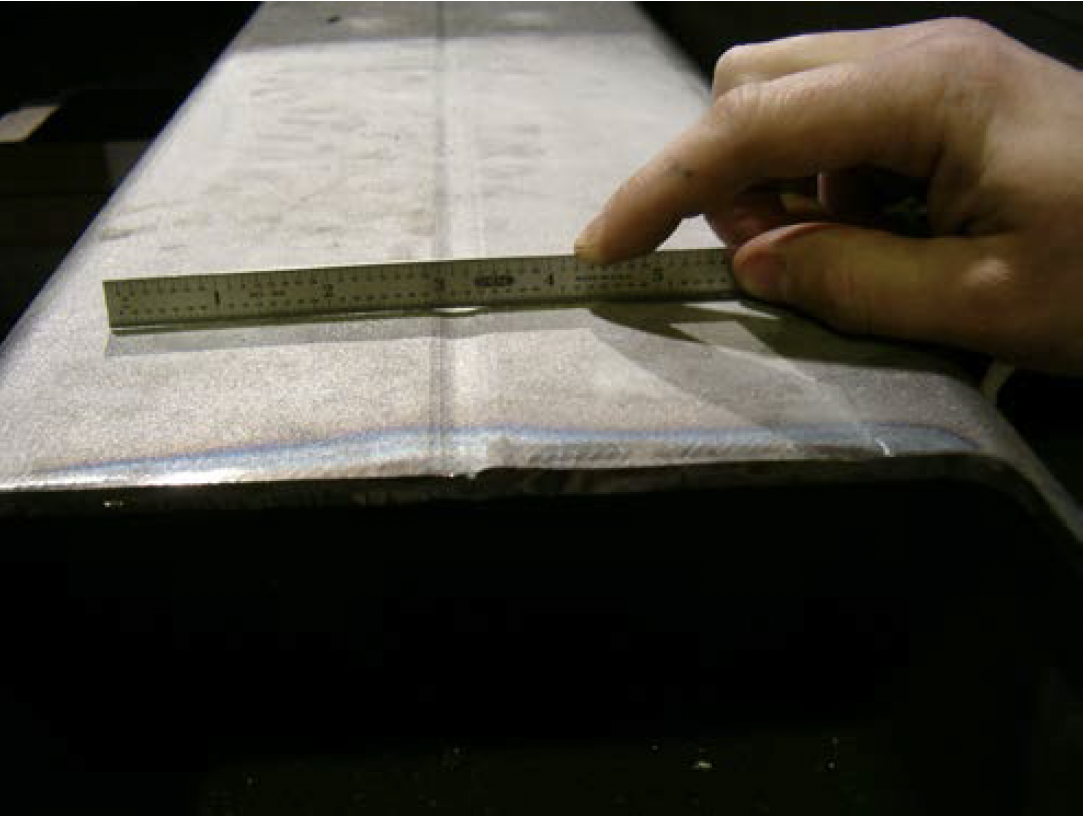
HSS manufacturers also generally concur that the longitudinal weld should fuse the HSS across the complete wall thickness. ASTM A500-13, however, only requires that … “The longitudinal butt joint of welded tubing shall be welded across its thickness in such a manner that the structural design strength of the tubing section is assured”. Since this specification notes that … “For square and rectangular tubing, the wall thickness requirements shall apply only to the centers of the flats” (which would not be construed as including a weld location), the amount of required through-thickness weld fusion is not specified. A slight concavity is not uncommon though, as shown in Figure 2, and there are no acceptance or rejection criteria with ASTM A500 for the degree of fusion, or mis-alignment of edges either side of the weld.
Some cases of poor weld fusion have been found in the past, as illustrated in Figure 3. Extreme cases are evident visually, but partial lack-of-fusion can generally be detected by UT.

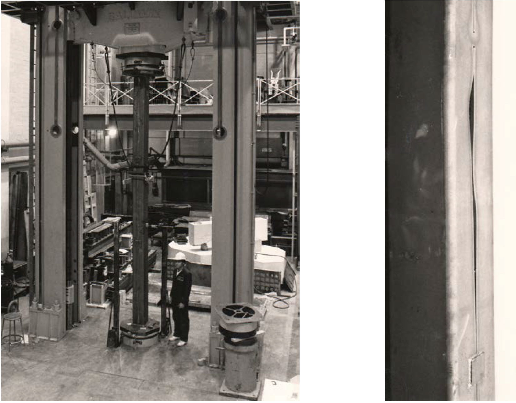
Since ASTM A500 stipulates that the HSS … “shall be welded across its thickness in such a manner that the structural design strength of the tubing section is assured”, the degree of through-thickness connection that is required depends on the HSS loading. If loaded in pure compression, as an axially compressed column, only intermittent partial connection is required – sufficient for the member to achieve global flexural buckling without suffering from local buckling of the open cross-section between points of connection. This has been illustrated experimentally by column tests in which the HSS was slit open along its length, to simulate zero through-thickness connection by a “seam weld”, and then loaded to failure in axial compression (Figure 4). Providing the open section was joined intermittently, across the free-standing edges, at reasonable (calculated) distances, global overall buckling could be attained.

While even an extreme case of zero through-thickness weld fusion can be repaired, by intermittent patches, to serve as an axially loaded HSS column, it is clearly dangerous to assume that such a member would be adequate under many other loading conditions, and especially at connections. ASTM A1085-13, on the other hand, states that … “The longitudinal butt joint of welded tubing shall be welded across its thickness”. Thus, with this new higher performance specification, any through-thickness weld fusion less than 100% is cause for rejection.
References
ASTM. 2010. “Standard Specification for Cold-Formed Welded and Seamless Carbon Steel Structural Tubing in Rounds and Shapes”, ASTM A500/A500M–10, ASTM International, West Conshohocken, PA.
ASTM. 2013a. “Standard Specification for Cold-Formed Welded and Seamless Carbon Steel Structural Tubing in Rounds and Shapes”, ASTM A500/A500M–13, ASTM International, West Conshohocken, PA.
ASTM. 2013b. “Standard Specification for Cold-Formed Welded Carbon Steel Hollow Structural Sections (HSS)”, ASTM A1085–13, ASTM International, West Conshohocken, PA.
Sun, M. and Packer, J.A., 2014. “Direct-Formed and Continuous-Formed Rectangular Hollow Sections – Comparison of Static Properties”, Journal of Constructional Steel Research, Vol. 92, pp. 67-78.
August 2014