HSS KT-Connections
By Jeffrey A. Packer
Bahen/Tanenbaum Professor of Civil Engineering, University of Toronto, Ontario, Canada
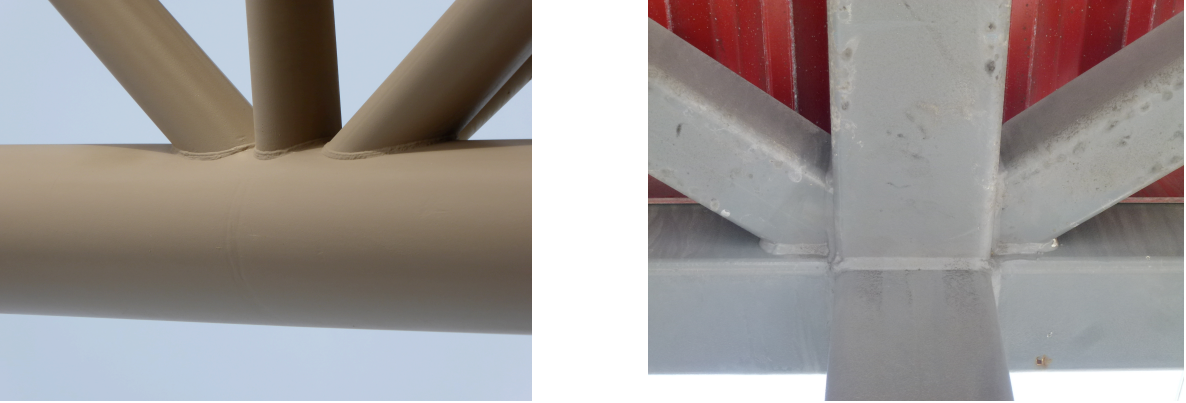
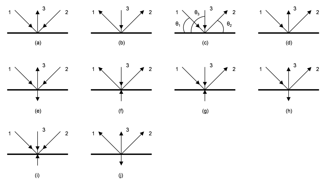
HSS Warren trusses frequently have K-connections that are modified by the introduction of a third branch member, usually a vertical, to form a so-called KT-connection, as illustrated in Figure 1. The design of such connections is beyond the scope of the Specification for Structural Steel Buildings (AISC 2010, 2016), AISC Design Guide No. 24 (Packer et al. 2010) and the most recent CIDECT Design Guide (Packer et al. 2009). There are a large number of possible member configurations and loading arrangements for KT-connections, so a simple, unique design method is not available. Some of the possible load combinations on the three branch members of a KT-connection are shown in Figure 2.

Left Image (a) Round HSS KT-connection | Right Image (b) Rectangular HSS KT-connection

Gapped KT-Connections
If all three branches have gaps between them at the chord connecting face, methods of analysis for various load cases are outlined below. The procedure is based upon splitting the KT-connection into participating K- and Cross-connections, then checking using AISC 360-10 Chapter K. Branch members participating in multiple sub-connection types need to have their total utilization checked to ensure that it is less than unity by linear addition of their respective utilizations in each sub-connection.
Case 1: In Figures 2(a) and 2(b), the force in branch 3 can be split into two parts, each of which balances the vertical components of the forces in branches 1 and 2. Thus, the total connection can be divided into two K-connections, consisting of branches 1 and 3, and branches 2 and 3. These two K-connections can then be checked individually, with an added check on the total utilization of branch 3. (Note that the N-connection is considered a special case of the more general K-connection.)
Case 2: In Figures 2(c) and 2(d), two neighboring branches have the same force sense. The free-body diagram of KT-connection forces can be broken into constituent sub-connections, as illustrated in Figure 3, and analyzed again as two K-connections. Branch 2, in this case, would have to be checked for its total utilization, since it participates in two separate K-connections.

Case 3: In Figures 2(e) and 2(f), the free-body diagram of KT-connection forces can be split into constituent free-body diagrams consisting of a Cross- (or X-) connection plus two K-connections, as illustrated in Figure 4. Branch 3, in this case, would have to be checked for its total utilization, since it participates in three separate sub-connections.

Case 4: In Figures 2(g) and 2(h), the procedure is similar to Case 2, except an additional Cross-connection component will be introduced, thus making three separate sub-connections (or free-body diagrams), similar to Case 3.
Case 5: In Figures 2(i) and 2(j), the KT-connection is actually a single Cross-connection because all branch-force components normal to the chord are transferred through the chord.
If the vertical branch in a gapped KT-connection has zero (or near-zero) force in it, then it can be ignored and the connection treated as a K-connection, with the gap taken as the distance between the toes of branches 1 and 2 in Figure 2. This will be conservative because the presence of additional steel (branch 3) welded to the gap region will stiffen the connection.
Overlapped KT-Connections

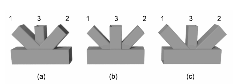
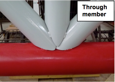
Overlapped KT-connections are actually much more probable than gapped KT-connections because the latter produce large positive noding eccentricities, which are likely to violate the Limits of Applicability for joint eccentricity in AISC 360 Tables K2.1A or K2.2A (AISC 2010). The common types of overlapped KT-connections are shown in Figure 5. The sequence of overlapping should follow the basic premise that narrower branches “sit on” (or frame into) wider members. If two overlapping branch members have the same width then the thinner should sit on the thicker branch (i.e., the thicker branch should be the “through member”). As with overlapped K-connections, overlapped KT-connections should have (at least) one branch fully welded all around its perimeter to the chord. Figure 6 shows an ideal fit-up for a round HSS overlapped KT-connection: branch 2 is a “through member”, welded entirely to the chord, branch 1 is profiled to overlap onto branch 2, then branch 3 is profiled to overlap both branch 1 and branch 2.

With Round HSS
The determination of the resistance of round HSS overlapped KT-connections can be handled in a similar way to Cases 1 through 5, described for gapped KT-connections, which involves splitting the free-body diagram of connection axial loads into sub-connections involving K- and Cross-connection types. Branch members participating in multiple sub-connection types need to have their total utilization checked to ensure that it is less than unity by linear addition of their respective utilizations in each sub-connection. The resistance of overlapped K-connections between round HSS is based only on the limit state of chord plastification (Equations K2-4 and K2-5 of AISC 360-10 Table K2.1). The amount of overlap (Ov), or negative gap (g), to be used in Equation K2-6, pertains to the two branches under consideration in a particular sub-connection. Again, if the vertical branch in an overlapped KT-connection has zero (or near zero) force in it, then it can be ignored and the connection treated as a K-connection.
With Rectangular (including Square) HSS
The resistance of rectangular and square HSS overlapped KT-connections can be determined on a branch-by-branch basis, in a similar manner to overlapped K-connections, using Equations K2-17 to K2-22 in AISC 360-10 Table K2.2. For example, in Figure 5(a) branch 2 is welded entirely to the chord, branch 1 is mitered to overlap onto branch 2 then branch 3 is mitered to overlap onto branches 1 and 2. The controlling limit state of branch local yielding for branch 3 involves a “code modification”, using beov effective width terms for both transverse walls, because these are both welded onto other branches; for branch 1 the checking can be performed as an overlapped K-connection with branch 1 overlapping branch 2; for branch 2, which is an overlapped member, the nominal available axial strength – expressed as a proportion of its yield strength – is not to exceed the nominal available axial strength of the overlapping branch, as a proportion of its yield strength, which is the basis of Equation K2-22 in AISC 360-10. A detailed design example illustrating this procedure is given by Packer (2014).
Since the design of HSS KT-connections can be reduced to the checking of component K- and Cross-connections, designers can obtain a great amount of help by using the tool “HSS Connex Online” which is available from the Steel Tube Institute website at: https://steeltubeinstitute.org
References
AISC. 2010. “Specification for Structural Steel Buildings”, ANSI/AISC 360-10, American Institute of Steel Construction, Chicago, IL, USA.
AISC. 2016. “Specification for Structural Steel Buildings”, ANSI/AISC 360-16, American Institute of Steel Construction, Chicago, IL, USA.
Packer, J.A. 2014. “HSS Truss Connections with Three Branches”, American Institute of Steel Construction Engineering Journal, Vol. 51, No. 3, pp. 145-153.
Packer, J.A., Sherman, D. and Lecce, M. 2010. “Hollow Structural Section Connections”, Steel Design Guide No. 24, American Institute of Steel Construction, Chicago, IL, USA.
Packer, J. A., Wardenier, J., Zhao, X.-L., van der Vegte, G.J. and Kurobane, Y. 2009. “Design Guide for Rectangular Hollow Section (RHS) Joints under Predominantly Static Loading”, CIDECT Design Guide No. 3, 2nd edition, Comité International pour le Développement et l’Étude de la Construction Tubulaire, Geneva, Switzerland, ISBN 978-3-938817-04-9.
April 2016