Bending of Hollow Structural Sections
By Jeffrey A. Packer
Bahen/Tanenbaum Professor of Civil Engineering, University of Toronto, Ontario, Canada
1. Introduction
Curved steel hollow sections are widely used in the construction industry. The possible curvature of these members, however, is limited by the magnitude of distortion of the cross‐section during the bending process. This is particularly a concern for cold bending HSS members, as the resulting deformation from the fabrication process is much greater compared with other methods (Packer and Henderson, 1997). In an early study of this topic, Kennedy (1988) deduced minimum bending radii for cold rolling HSS, based on a series of experiments he established using three‐roller machines and deformation limits of 1% and 2% of the wall dimensions. These recommendations, for square and rectangular HSS, are given in Tables 8.2 and 8.3, respectively, of Packer and Henderson (1997). By using more specialized techniques, however, modern benders (typically a specialty subcontractor of the fabricator) can achieve even smaller radii than reported by Kennedy. A list of AISC member bender‐rollers across North America is obtainable from www.aisc.org/benders.
2. Bending Techniques
The American Institute of Steel Construction (AISC) lists a number of available bending methods, which are described below (Alwood 2006). It is important to note that some are common to the steel construction industry, while others are more common to the automobile or manufacturing industries.
2.1 Pyramid Rolling or Cold Bending
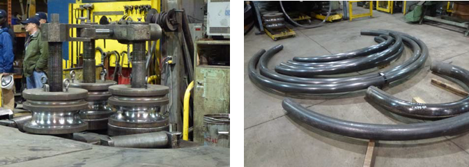
Cold bending using “pyramid rollers” is a common curving technique used to create HSS members with a constant radius. The method involves running the member through between three rollers, oriented in a pyramid shape as shown in Figure 1, varying the distance between the rolls with successive passes.

2.2 Gag Pressing or Point Bending
This is another form of cold bending that creates a curved member through application of a small number of point loads (typically up to two at the member third points) using a hydraulic ram. This method is usually used for cambering and curving beams to very large radii.
2.3 Hot Bending
Hot bending entails local heating, using a direct flame or a furnace, and then bending the member to the desired radius using a bending method. Hot bending is a common repair method for straightening bridge girders after structural damage from an event such as impact.
2.4 Rotary‐Draw Bending

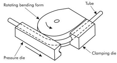
With this method the HSS is clamped into a form and then drawn around a die with a given bend radius (see Figure 2). Different bends require dies with different radii which means that this method is typically only used for large‐scale production projects requiring many of the same bend. Rotary‐draw equipment can bend members to very small radii and is used to create complicated bends in smaller products for the machine and parts industry. This method can significantly mitigate flattening and distortion.
2.5 Induction Bending
Similar to hot bending, this method involves heating the HSS member. However, this method only heats a short length of the member and uses an electric coil around the HSS to create the heat, as opposed to a furnace or flame. Once it is heated, the member is drawn through a process similar to rotary‐drawing and quenched with water directly afterwards. Tighter bends can generally be achieved with induction or hot bending than alternate cold bending methods.
2.6 Synchronized Incremental Cold Bending
In this method, similar to technique 2.2, loading is applied at multiple points along the length in a highly synchronized fashion. This process generally involves multiple load cycles to create the desired radius, but can result in tight radii with minimal distortion.
Based on the information on websites of various benders, the most commonly used methods in industry at present appear to be pyramid rolling, gag pressing, rotary‐draw bending and induction bending (CMRP, 2012; Hodgson 2012; Kubes 2012; Tulsa 2012).
3.0 Minimum Bending Radii
The minimum bending radius achievable for HSS depends on many factors including:
(i) The bending method – note that cold bending methods are the most common.
(ii) Whether the side walls are properly supported during bending (by using rolls that fit the section shape); i.e. the equipment used is influential, as is the operator.
(iii) The shape of the HSS being curved – round, square, rectangular (and the ratio of wall heights for the latter). Pipe or round HSS is easier to curve than square/rectangular HSS (Marks et al., 2002). When bending a rectangular HSS about the “weak axis” (see below), a greater B/H ratio produces larger concavity distortions on the inside radius wall (Smith and King, 2002).
(iv) The wall thickness, or the slenderness D/t, H/t or B/t. A lower bend radius is achievable with stockier (thicker) walls, without wall distortions (Smith and King, 2002).
(v) The bending axis, if rectangular HSS (“strong” versus “weak” axis bending). Bending about the strong axis (or “the hard way”), although requiring more force, makes a rectangular HSS less susceptible to deformation problems, relative to the same rectangular HSS bent about the weak axis (or “the easy way”). (Smith and King, 2002).
(vi) The yield strength of the steel. Over‐straining and hence deformation of a member during the cold bending operation is more likely to occur when using lower strength steels, compared to high strength steel (Bjorhovde, 2006).
(vii) The allowable distortions of the HSS walls, and any permitted surface scratching, etc. This may be particularly important for Architecturally Exposed Structural Steel (AESS).
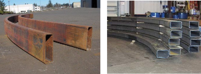
Because of these many variables, one must be very cautious in assuming that a particular bending radius can be attained and one should check a particular member curvature with specific benders to verify their capabilities. Also bear in mind that the bending radius dimension must be mutually understood; usually the bending radius refers to the member centerline for pipe and rounds, but often refers to the outside radius for square and rectangular HSS. For rectangular HSS, it is important to differentiate between bending HSS “the easy way” versus “the hard way”, as described in (v) above and illustrated in Figure 3. Furthermore, when bending HSS the member needs to be supplied “over‐length”, as not 100% of the member can be curved; smaller sections need about 1’‐0” each end and larger sections need up to 6’‐0” each end (Marks et al., 2002). More bending tips are also available on the AISC website.

Left Image (a) Bent “the easy way” | Right Image (b) Bent “the hard way”
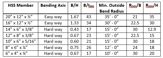
Since benders tend to consider their process both a “science” and an “art”, as well as “intellectual property”, published data for HSS bending radii are generally only given as a guide. Nevertheless, the minimum bending radii given in Table 1 for rectangular HSS are indicative of contemporary cold bending practice for ASTM A500. Barnshaws Metal Bending (2012), which claims to be the world’s largest steel bending company, provides an on‐line “bending calculator”, which gives the minimum inside bend radius for a multitude of structural shapes, including HSS. While this may prove a useful tool, this U.K. company might not be representative of North American practice.

4. Costs
Although most construction costs are still given per unit weight of material, the cost of bending is largely determined by the time it takes to bend a member. Hence it is better and more accurate to approach the cost on a per bent member basis, irrespective of member weight. There will be some economies with repetition and handling lighter members. Bender/rollers will quote to potential clients on a particular job, but a very general rule of thumb provided in AISC’s “Modern Steel Construction” is to allow $0.25/lb for steel bending on smaller projects (Marks et al., 2002), but this should be increased for AESS applications or multi‐directional bending.
5. References
Albina Pipe Bending Co., 2012. http://www.albinapipebending.com. Accessed 11‐10‐2012.
Alwood, T.A. 2006. “What Engineers and Architects should know about Bending Steel”, Modern Steel Construction, American Institute of Steel Construction, May issue.
Barnshaws Metal Bending, 2012. http://www.barnshaws.com/capacity‐calculator18.php#step2. Accessed 31‐12‐2012.
Bjorhovde, R. 2006. “Cold Bending of Wide Flange Shapes for Construction”, Engineering Journal, American Institute of Steel Construction, Vol. 43, 4th. Quarter, pp. 271 – 286.
Chicago Metal Rolled Products, 2012. http://www.cmrp.com. Accessed 11‐8‐2012.
Hodgson Custom Rolling Inc., 2012. http://www.hcrsteel.com. Accessed 11‐11‐2012.
Kennedy, J. B. 1988. “Minimum Bending Radii for Square & Rectangular Hollow Sections (3‐Roller Cold‐ Bending)”, CIDECT Report 11C‐88/14‐E, University of Windsor, Windsor, Canada.
Kubes Steel, 2012. http://www.kubesteel.com. Accessed 11‐11‐2012.
Marks, D., Wendt, G. and Libby, E. 2002. “Bending Steel”, Modern Steel Construction, American Institute of Steel Construction, June issue.
Packer, J. A. and Henderson, J. E. 1997. “Hollow Structural Section Connections and Trusses – A Design Guide”, 2nd. Edition, Canadian Institute of Steel Construction, Toronto, Canada.
Smith B. and King, M. 2002. “Bending Square and Rectangular Tubing – Modern Science or Ancient Art?”, TheFabricator.com, Fabricators & Manufacturers Association Intl.
Tulsa Tube Bending, 2012. http://www.ttb.com. Accessed 12‐30‐2012.
Whitefab Inc., 2012. http://www.whitefab.com. Accessed 12‐30‐2012.
March 2018