Don’t Get Bent Out of Shape: Minimizing Distortion in Curved HSS Members
By Mike Manor, PE, MLSE
Technical Consultant, Steel Tube Institute
April, 2024
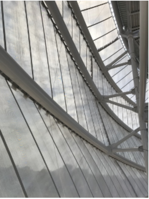
Allianz Field
Photo Credit: Walter P. Moore
Curving HSS is a specialty craft honed through many years of practice by bender/rollers. This highly specialized process has many nuances that make it more of an art form to produce aesthetically pleasing curved steel HSS shapes rather than merely being a mechanical process as a means to an end. Of course, those good looks don’t come easy as it could end up going south if not handled with care. Distortion of the HSS cross section is the biggest issue to deal with to ensure adequate strength, stiffness, and aesthetics of the final product. This article will explain what distortion is, how to prepare for a successful bending project, and finish with some helpful rules of thumb for successful projects.
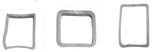
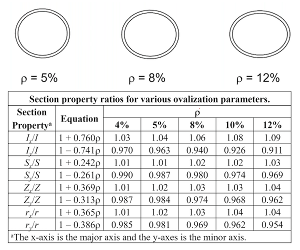
Steel is a very ductile material meaning it has high strength and yet a fantastic memory of how to return to its original shape when the load is removed. However, the very idea of bending a piece of steel runs completely counter to this idea as it must be strained beyond its yield point into the plastic region to form a permanent curve. When in the final form, it looks great, as can be seen at Allianz Field in Figure 1 (see Case Study and Interview about Allianz Field in the reference section), but getting there can be difficult. The largest challenge is distortion of the cross section during the bending procedure. According to AISC Design Guide 33, distortion is the deviation of the steel cross-section from its original shape, which occurs in every bent member to some degree. Round HSS members typically flatten to an oval shape (see Figures 3 and 5). For rectangular HSS members, distortion can appear as localized buckling in the web when bending against the strong axis or as a series of waves or ripples in the compression flange when bending against either the strong axis or weak axis. See Figures 2 and 3. Bending against the strong axis is also referred to as the “hard way” while weak axis is the “easy way”. Additionally, rectangular HSS can simultaneously display growth and shrinkage on opposite sides of the neutral axis resulting in an isosceles trapezoidal cross-sectional shape (referred to as keystoning) and thus the radiused corners are no longer square (≠90°). Finally, rectangular members with large depths in the plane of bending can exhibit shrinkage of the overall depth. For example, an HSS20x12 bent the hard way could demonstrate up to 5/8” shrinkage in the 20” face.
CIDECT Report 11C-88-14-E
There are many methods for bending/rolling HSS into curved shapes. Hot rolling can achieve much tighter curves (smaller radii) than cold rolling, but generally has a higher cost meaning it is not always the best option for all cases. Within hot and cold rolling, there are many methods used by bender/rollers. The STI article “HSS Bending of Hollow Structural Sections” explains the various processes for HSS in much greater detail as well as “AISC Design Guide 33: Curved Member Design.” The key item to understand is that each process has its own specific tools and techniques that are required. Many techniques require having more than one of each tool type to vary the bend radius. Additionally, each bender/roller has proprietary methods and machinery, thus the capabilities of each shop vary. This results in quite an investment of equipment, so each shop has developed their own specialty areas resulting in different maximum/minimum radii capabilities on various member sizes. It is recommended to reach out to a bender/roller to see what is possible for each design situation to determine the best way to achieve the desired design goal. For those unsure of whom to contact, AISC Design Guide 33 contains a list of bender/rollers across the country, so please give them a call.
Realistically, bending the HSS members is the easy part. The hard part is preventing the distortion while preserving the aesthetics, original cross-section dimensions, and structural properties of the member. Gentle curves with a large radii likely won’t require much to resist the distortion, but more demanding bends may require the use of mandrels or other non-compressible filler materials such as sand inside the HSS to prevent collapsing of the HSS shape during the bend process. These materials are then removed when the process is complete. Be aware that the use of a mandrel or other internal bracing material significantly increases the cost of the bend.

AISC Design Guide 33
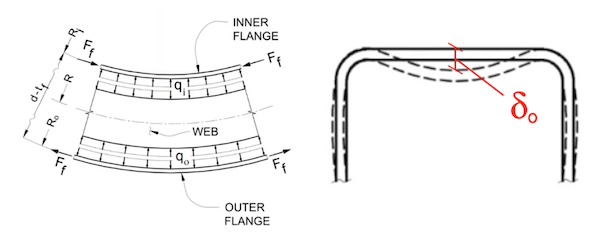
There are three sources of distortion to be aware of. First is the contact from the bending machine that imparts a concentrated point load on the steel member. Second are stresses created within the member during the bending process such as web shear buckling or local buckling in the flanges or webs. Third are radial forces, shown as qi and qo in Figure 4, which occur as components of the internal flange forces (Ff) making up the resisting moment couple. In a straight member, the flange forces would oppose each other in static equilibrium, but the curvature makes a portion of these forces act on the member web in the direction perpendicular to the member longitudinal axis. However, no matter what methods are used to combat distortion, the geometry of the HSS shape may still govern what is possible. The ratio of width-to-thickness or diameter-to-thickness will affect the amount of distortion during a bend. For a given HSS size, bending radius, and bending process, there will be a minimum wall thickness requirement that may be thicker than what is needed by structural analysis of the in-place design loads. In other words, the lightest HSS section may not always be the final member size as the bender/roller may request the substitution of a thicker member to ensure a successful final product. Contacting a bender/roller early in the design process helps minimize this back and forth coordination while ensuring an appropriate thickness is specified in the design bid documents.
AISC Design Guide 33
The reality is that every time a member is curved, some amount of distortion is unavoidable. Additionally, any imperfections of the original member will be amplified by the bending process. Thus, some distortion is acceptable (and may even be imperceptible), but how much distortion is too much? The AISC Code of Standard Practice (COSP) provides tolerances for global dimensions of curved members by pointing to the applicable camber and sweep tolerances in the pertinent ASTM standard such as A500 for HSS. See the STI Tolerance Guide in the reference section for the quantified tolerance values and how they are measured. Unfortunately, the COSP does not address tolerance for cross sectional distortion. Therefore, the tolerances for distortion must be established by the design team and specified in the contract documents. The question that comes to mind then is “What tolerances are acceptable for bending?” The answer to that depends on the structural and architectural design requirements for the member. Often the architectural aesthetic requirements tend to be more stringent than the structural requirements, especially in the case of Architecturally Exposed Structural Steel (AESS). Another resource to consult is from the Pipe Fabrication Institute (PFI) Standard ES-24 which has a discussion on distortion tolerances.
AISC Design Guide 33
So how is distortion measured? Figure 3 shows measurements and equations for calculating ovality for round HSS and distortion of the web and compression flanges in rectangular HSS. Starting with rectangular HSS shapes, the A500 tolerance for flats greater than 5-1/2” is ±1% of the largest flat dimension. These limits work well for straight members but are difficult to achieve when bending especially for tight small radius bends. Based on experience of many roller/benders, a post-bending tolerance limit of 1% to 2% generally produces good results. As an example for an HSS8x8 with 2% distortion, that means the b1 value in Figure 3 would be 8.16in. For AESS, a tolerance of ±1/2” seems to work well for all distortion types. Circling back to round HSS, ASTM A500 lists a tolerance of ±0.75% at straight members for diameters greater than 2” which is much smaller than can be achieved after bending. Ovality of 5% to 8% are generally achievable in most situations. Figure 5 demonstrates how various percentages of ovality visually appear for the purpose of determining AESS tolerance limitations. Finally, consideration of these tolerances must be kept in mind when connecting curved members to straight members. For example, alignment of end to end splices must consider a combination of the different tolerances for fitting up the final distorted cross sectional shape to the undistorted shape during steel erection. Butt welds may prove difficult to install and may not provide an aesthetically pleasing result. For much more in depth information on distortion, see chapters three and four of “AISC Design Guide 33: Curved Member Design.” Also see the resource section at the end of this article for many informative resources that help clarify both the bending process and the effects of distortion.
Rules of Thumb
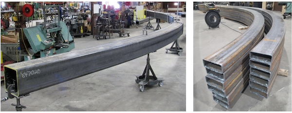
Photo Credit: Max Weiss Company
As stated previously, bending HSS steel members is an art form that is difficult to predict and accomplish while limiting visible buckling and distortion. The bender/rollers have developed their knowledge and honed their techniques over decades. Each bending project is a unique situation with a lot of variables to consider and there may be multiple ways to achieve the desired goal. Thus, the bender/rollers are the experts to call when working on a project (the earlier the better) to determine the best course of action toward a successful project. However, the following rules of thumb can be helpful to get an idea of what is in the realm of possibility when bending HSS. The list below is merely meant as a guide for many bending cases trying to balance what can be achieved with associated costs for the bending process options but may not always hold true for all situations. Additionally, these may be conservative limits in some cases where certain bending technologies can push the boundaries much further.
- Close-shaped members such as HSS are much more resistant to distortion than open shapes such as wide flanges.
- Round HSS members are much more resistant to distortion than rectangular HSS members with flat sides.
- Generally, HSS cross-sections that are efficient in resisting local buckling are also efficient for resisting distortion (i.e. b/t ratio considerations along with the limits in chapter B of the AISC 360 Specification). Reducing the width-to-thickness ratios at the flange and web increases resistance to distortion.
- Consider specifying a minimum 3/8” nominal thickness for curved members to provide a reasonable local buckling resistance to the forces exerted by the bending machines. Increasing HSS wall thickness may be more cost effective than using mandrels to reinforce the HSS member during the bending process.
- Consider a maximum nominal thickness of 1/2” to 5/8”. Thicker walls simultaneously increase the HSS section properties and the forces required to bend the section especially for tight bends with small radii.
- Recommended distortion limits:
a. Rectangular HSS 1% to 2%
b. Round HSS 5% to 8% - See AISC Design Guide 33: Curved Member Design Table 3-2 and Section 3.4.3 for an example list of HSS sizes with successful bend radii.
- At end splices in HSS curved members, consider relative distortion between the members during the design phase for feasibility of alignment when determining the splice location and connection type. Similar bend radii tend to have similar distorted cross-sections (but not exactly the same) while large differences in radii can have drastically different cross-sections especially between straight and curved members. Locate the splice in straight segments of HSS away from the curved portions when possible.
Example Calculations for HSS Members
In STI’s webinar titled “Curved HSS Members,“ Bo Dowswell, the author of AISC Design Guide 33, discusses the curving of HSS members. See the link for this webinar in the resource section. In the presentation, he gives an example of how to calculate the effect on HSS flexural strength of a rectangular member based on a measured distortion of the flange equal to the nominal thickness or 1.88% distortion. He demonstrates how to calculate the effective width-to-thickness ratio (λe) of the distorted compression flange. As a spoiler, it turns out that despite a 34% increase (λe = 1.34λ), the HSS member still meets the requirements for AISC 360-22 Table B4.1b for a compact flange and thus did not lose any strength due to the distortion of the cross-section.
To expand on Mr. Dowswell’s example, following is another example reversing the process to determine the allowable amount of initial distortion an HSS rectangular shape can withstand while still retaining full compactness of the flexural flange. Refer to Figure 4.
Given:
- ASTM A500 Gr. C (Fy = 50ksi)
- HSS 20x8x3/8 (tnominal = 0.375in, tdesign = 0.349in)
- 2% initial distortion of the bending compression flange
- HSS vertically curved member bent the hard way
HSS Geometry
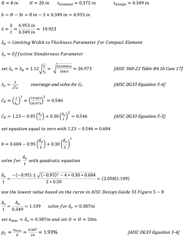
To keep the flange of a curved HSS20x8x3/8 compact and thus not reduce the member flexural strength, the maximum initial distortion is 0.387in which is a maximum 1.93% flange distortion. If the initial distortion is larger, then the member must be designed for the effects of flange local buckling per AISC 360-22 Section F7.2.
Conclusion
Curved HSS steel members can be a very aesthetically pleasing addition to the design of structures, but care must be taken to specify appropriately sized members. All curved members will end up with cross-sectional distortion to some degree, however, a good design comes from awareness of the effect that member strength and stiffness may have on the bending process. Keep in mind there are tolerances and rules of thumb to start the design moving in the right direction. And of utmost importance, remember that the bender/rollers are the experts with invaluable knowledge and experience, so give them a call to determine what is possible for the project and the best bending method for the job.
Thank you to the following bender/rollers for their review and collaboration with this article:
- Ken Pecho, Chicago Metal Rolled Products (https://www.cmrp.com/)
- Al Sanders, Max Weiss Company (https://www.maxweiss.com/)
References
- AISC Publication: “Design Guide 33: Curved Member Design”
- STI Webinar: “Curved HSS Members” by Bo Dowswell, October 2019
- STI Article: “Bending of Hollow Structural Sections” by Dr. Jeffrey Packer
- STI Article: “Heat Treating HSS” by Dr. Jeffrey Packer
- STI Article: “Architecturally Exposed Hollow Structural Sections – Part Two – Connections, Finishes and Curved Members – By Cathleen Jacinto
- STI Interview: “Allianz Field: How Collaboration and Round HSS Led to an Iconic Stadium”
- STI Case Study: “HSS Case Study: Allianz Field—A Modern Stadium Marvel in St. Paul”
- STI Publication: “Methods to Check Dimensional Tolerances on Hollow Structural Sections”
- STI Article: “Insights Into the Art and Science of Bending Hollow Structural Sections“
- PFI Publication: “ES-24 Pipe Bending Methods, Tolerances, Process and Material Requirements”
- ASTM Publication: “ASTM A500/A500M-23 Standard Specification for Cold-Formed Welded and Seamless Carbon Steel Structural Tubing in Rounds and Shapes”
- AISC Publication: “Code of Standard Practice for Structural Steel Buildings and Bridges” (AISC 303-22)
- STI FAQ: “Bending of HSS”
- CIDECT Publication: “Design Aids – Minimum Bending Radii for Square and Rectangular Hollow Structural Sections Subjected to Cold Bending CIDECT Report 11C-88-14-E” by J.B. Kennedy
Insights Into the Art and Science of Bending Hollow Structural Sections
Learn more about bending HSS from expert Ken Pecho, sales/project engineer & technical operations of Chicago Metal Rolled Products. Read his expert insights into the practice, different styles of bending, the importance of getting bender rollers involved early and his advice for growing in the industry.