Design Example: HSS Overlapped K-Connections With and Without the Hidden Toe Weld
By FORSE Consulting, LLC
Technical Consultants, Steel Tube Institute
Recent research sponsored by the Steel Tube Institute and performed by Bu and Packer1 has shown that welding or not welding the hidden toe in rectangular HSS overlapped K-connections with partial overlap (Ov < 100%) does not make an appreciable difference in the connection capacity. The conclusions of the research are published in an ASCE paper (Bu and Packer, 2023) and STI Article, Overlapped HSS K-Connections: To Weld or Not Weld the Hidden Toe? Research finds that welding of the hidden toe is considered unnecessary for partial overlaps, provided (i) full-strength branch-to-chord welds are used elsewhere that develop the yield strength of the branch, and (ii) design provisions per the STI Article are followed. The following design example demonstrates the recommended process for design of overlapped K-connections omitting the hidden toe weld. For the sake of comparison, the example will end with a calculation for the design of the weld all-around the branches, including the hidden toe weld.
The benefit to omitting the hidden toe weld is to ease fabrication. Many fabricators prefer to tack weld both branches and then fully weld them. This cannot be done if the hidden toe needs to be welded. However, by not welding the hidden toe, the remaining weld sizes elsewhere on both branches may potentially need to be increased.
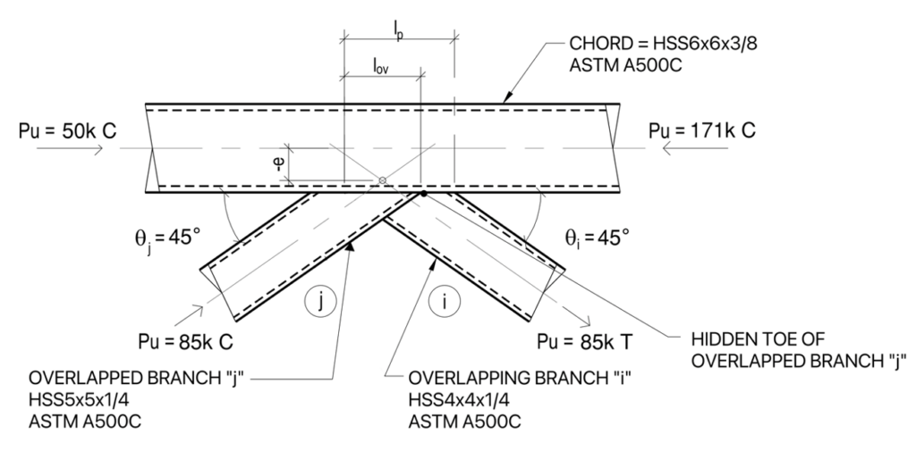
Limits of Applicability
[AISC 360-22 Table K3.2A]
| Chord: | B = 6″ | H = 6″ | tnom = 3⁄8 “ | tdes = 0.349″ |
| Overlapped branch: | Bbj = 5″ | Hbj = 5″ | tbj,nom = 1⁄4 “ | tbj,des = 0.233″ |
| Overlapping branch: | Bbi = 4″ | Hbi = 4″ | tbi,nom = 1⁄4 “ | tbi,des = 0.233″ |
Provide an overlap of lov=3.5″—overlap equals a negative gap
The overlap length is measured along the connecting face of the chord beneath the two branches.
Projected length of the overlapping branch on the chord: lp = Hbi ⁄ sinθi = 4 in ⁄ sin 45 = 5.66 in

The subscripts in this equation were changed from 1 to j and from 2 to i to match AISC convention.
e = –1.57 in
Connection eccentricity:
–0.55 ≤ e ⁄ H ≤ 0.25
e ⁄ H = –0.261 OK
Branch angle:
θ ≥ 30°
θ = 45° OK
This is not a requirement but is recommended for weld access.
Chord wall slenderness:
B ⁄ t ≤ 30
H ⁄ t ≤ 35
B ⁄ t = H ⁄ t = 17.2 OK
Branch wall slenderness:

Compression branch controls: Hbj ⁄ tbj = 21.5 OK
Width ratio:
Bb ⁄ B & Hb ⁄ B ≥ 0.25
B bi ⁄ B = Hbi ⁄ B = 0.667 OK
Aspect ratio:
0.5 ≤ H ⁄ B & Hb ⁄ Bb ≤ 2.0
H ⁄ B = Hb ⁄ Bb = 1.0 OK
Overlap:
25% ≤ Ov ≤ 100%
Ov = lov ⁄ lp = 3.5 in ⁄ 5.66 in = 62% OK
Branch width ratio:
Bbi ⁄ Bbj ≥ 0.75
Bbi ⁄ Bbj = 0.8 OK
Branch thickness ratio:
tbi ⁄ tbj ≤ 1.0
tbi ⁄ tbj = 1.0 OK
Material strength: Fy = 50 ksi ≤ 52 ksi OK
Ductility:
Fy ⁄ Fu = 0.81
Note: ASTM A500C is acceptable.
All limits are met; therefore, the equations of AISC 360-22 Table K3.2 are appropriate.
The hidden toe of the overlapped member will not be welded; therefore, refer to the STI article, the “Overlapped HSS K-Connections: To Weld or Not Weld the Hidden Toe?” by Dr. Jeffrey A. Packer (2023) for the suggested design procedure. Per the article, the design checks for an overlapped K connection include local yielding of the branches due to uneven load distribution (modified per the STI article) and local yielding of the chord due to combined loading of axial load in the chord and moment produced by eccentricity. The hidden toe weld may be eliminated provided that the remaining branch welds develop the strength of the connected branch wall.
1. Local Yielding of the Branches Due to Uneven Load Distribution
Check the limit state of local yielding of branches due to uneven load distribution with modifications per Section 4 of the STI article per Packer (2023).
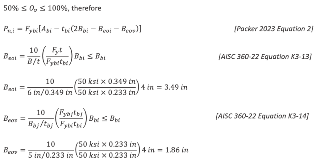
From Packer (2023), when Ov < 100%, ϕ = 1.00
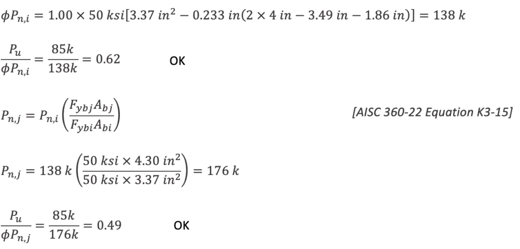
2. Local Yielding of the Chord Due to Combined Loading
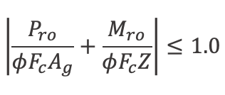
Per Packer (2023), one condition of eliminating the hidden toe weld is that effects of the connection eccentricity must be included when checking the chord.
Mro = 2 × 85 k × cos 45 × 1.57 in = 189 k – in
Per Packer (2023), ϕ = 1.00 when Ov < 100%

3. Branch-to-Chord Weld Design
The impact of not welding or welding the hidden toe will be compared in this weld design example as shown in Case A and B, respectively.
Case A) Weld Calculation: Omitting the Hidden Toe Weld
Per Packer2, welding the hidden toe can be considered unnecessary provided that branch-to-chord welds elsewhere develop the yield strength of the connected branches. Therefore, in order to eliminate the hidden toe weld, all other welds at both branch members shall be designed to develop the HSS wall in tension yielding. Check fillet welds.
tbj = tbi = 0.233 in
[AISC 360-22 Equation J4-1 & J4-6]
ϕRn = ϕFytb = 0.9 × 50 ksi × 0.233 in = 10.5 k ⁄ in
For the tension branch, the directional strength increase factor (kds ) must be taken as 1.0.
Weld size per inch of weld length:

At the compression branch, kds is allowed to be greater than 1.0.

or use a 1/2 in fillet to match branch i.
Therefore, if the hidden toe is not welded, provide ½” fillet welds at both branches all-around except not at the hidden toe of the overlapped tension branch.
Case B) Weld Calculation: Including the Hidden Toe Weld
For comparison, find the fillet weld size required if the hidden toe is welded and the effective length of weld can be used to resist the applied forces.
Calculate the effective length of the weld at member j (the overlapped member) including the weld at the hidden toe.
θj ≤ 50°, Bbj / B = 0.833 ≤ 0.85, therefore:
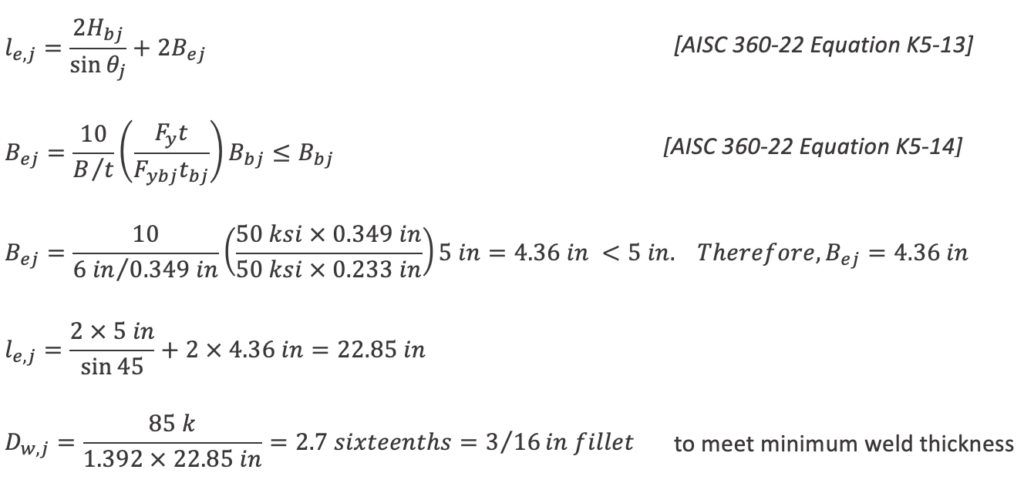
Weld at i (overlapping) member:
When 50% ≤ Ov ≤ 80%:

Beoi = 3.49 in from equation K3-13 calculated above
For Beov, when 180 – θi – θj > 50, Beov ⁄ 2 ≤ Bbi ⁄ 4 maximum
180 – 45 – 45 = 90 therefore Beov = 2 × 4 in ⁄ 4 = 2.00 in maximum
Beov = 1.86 in from equation K3-14 calculated above

For 5/16” fillet weld:
Weld strength for tw = 5/16” weld:
ϕRn = 1.392Dle,i = 1.392(5)(14.61 in) = 61 k [AISC 15th Ed Manual Eqn 8-2a]
ϕRn = 101 k > Ru = 85 k OK
Therefore, where the hidden toe weld is included, provide 5/16” fillet welds at both branches all-around.
In this particular example, if the hidden toe is welded as shown in Case B, the branch-to-chord fillet weld size is smaller. Omitting the hidden toe weld in Case A results in larger branch weld sizes elsewhere in this connection, but may be more beneficial in fabrication of the HSS truss. Note that the maximum weld size for Case B is that given by Case A, because if the weld develops the branch member wall, then the likely connection failure mode is branch local yielding and the weld is non-critical.
References
Bu, X.-D. and Packer, J.A., “Hidden Toe Welds in RHS-to-RHS Overlapped K-Connections”, Journal of Structural Engineering, American Society for Civil Engineers, 2023.
Packer, J.A, (2023, May). “Overlapped HSS K-Connections: To Weld or not Weld the Hidden Toe?,” Steel Tube Institute.
Disclaimer: While this information is believed to be accurate, it has not been prepared for conventional use as an engineering or construction document and should not be used or relied upon for any specific application without competent professional examination and verification of its accuracy, suitability, and applicability by a licensed engineer, architect, or other professional. The Steel Tube Institute and its consultants disclaim any liability arising from information provided by others or from the used of the information contained in this document.