Overlapped HSS K-Connections: To Weld or Not Weld the Hidden Toe?
By Jeffrey A. Packer
Bahen/Tanenbaum Professor of Civil Engineering, University of Toronto, Ontario, Canada
For a proper welded joint to the chord member, an overlapped rectangular HSS K-connection will have one branch welded on top of the other, with a “thru branch” or “overlapped branch” having a single miter cut welded solely to the chord. Then, the “overlapping branch” may have a portion welded to the chord and a portion to the overlapped branch, forming a partially overlapped K-connection (Figure 1(a)), or the overlapping branch may be welded directly to the overlapped branch, forming a fully overlapped K-connection (Figure 1(b)). The overlap, Ov, in Figure 1 is defined in Section K3.1 of the Specification (AISC, 2022) and is further illustrated in the accompanying Commentary Figure C-K2.1.

Left image: (a) Partially overlapped, Ov < 100%
Right image: (b) Fully overlapped, Ov = 100%
In an overlapped K-connection, the toe of the overlapped branch is covered beneath the overlapping branch and is called a “hidden toe”, as shown in Figure 1. With the hidden toe welded to the chord, the stiffness and strength of the connection are not compromised. However, welding the hidden toe to the chord complicates the fabrication procedure and is difficult to verify by inspection. The necessity of welding the hidden toe in a rectangular HSS-to-HSS K-connection has been greatly debated. Consequently, a research project has been sponsored by STI (in collaboration with AISC, AISI, CISC and Atlas Tube) to study the conditions for welding the hidden toe. This article summarizes this investigation, which is described at greater length by Bu and Packer (2023).
At present, amongst all codes and standards internationally, only Section K5 of the Specification (AISC, 2022) gives specific advice on when the hidden toe may be left unwelded, while CIDECT DG3 (Packer et al., 2009), IIW (2012), ISO 14346 (ISO, 2013) and the Eurocode 3 pre-Norm (CEN, 2021) include a failure mode (branch shear) that specifically considers the welding of hidden toes. Traditionally, the design of rectangular HSS-to-HSS overlapped K-connections has been based on one limit state; i.e., local yielding of the overlapping branch member, with a subsequent utilization check of the overlapped branch (e.g. Table K3.2 of AISC 360-22). From 2009 though, CIDECT/IIW/ISO – and now CEN (2021) – design recommendations for rectangular HSS-to-HSS overlapped connections have included the additional limit states of chord yielding (which could be considered a chord capacity check rather than a connection failure mode) and branch shear. The failure modes associated with these three limit states are illustrated in Figure 2. Thus, the project described herein had the following two-fold objectives:
- To identify the conditions where the hidden toe can be left unwelded, without significantly compromising the connection strength; and
- To determine if the design method for overlapped rectangular HSS K-connections in the current Specification (AISC, 2022) needs any revision (especially regarding the inclusion of the branch shear limit state).

Left image (a) Local yielding of branches
Middle image (b) Local yielding of chord
Right image (c) Branch shear
Experimentation

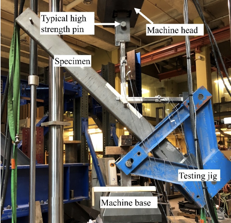
Details of all prior rectangular HSS-to-HSS K-connection tests, dating back to the 1970s, were collated, but in these previous tests of overlapped connections it was not recorded whether the hidden toes were welded or not. Five full-scale K-connection specimens were hence designed for testing in the laboratory, with one of the main goals being to achieve branch shear failure in the test specimens in order to evaluate how the effect of hidden toe welds is reflected in the branch shear limit state. All specimens had a high overlap ratio, Ov, which reduces the combined branch shear area, rectangular branches with the large dimension transverse to the chord, and the presence of a hidden toe weld was varied as well as the branch load sense. Quasi-static tests on the isolated K-connections were performed within a universal testing machine using a triangular-shaped, special-purpose, self-reacting testing jig (Figure 3) that produces the same magnitude of load in each branch, but with one in tension and one in compression.
The tests revealed that the presence of a hidden toe weld enhanced the connection capacity, but only by approximately 6%. Also, specimens that had tension loading in the overlapping branch proved to be stronger than their counterparts with tension in the overlapped branch. However, such experimental data is very limited, so numerical analysis was then used to create a large number of “numerical tests” over a broad parameter range.
Finite Element (FE) Modeling
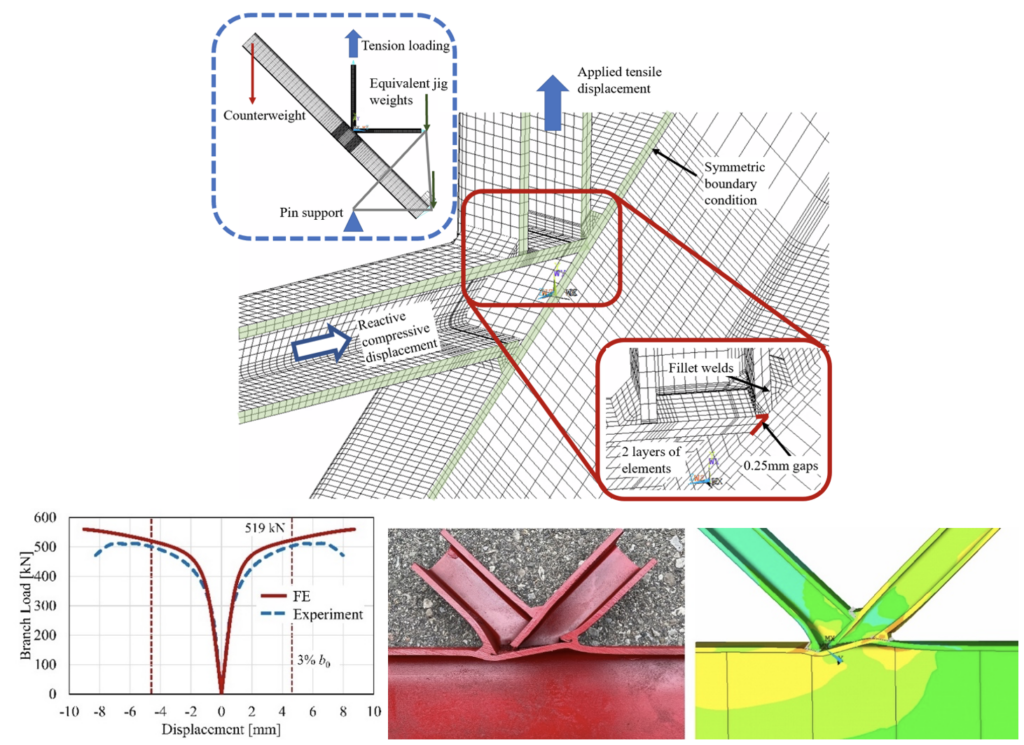
FE models of the complete testing arrangement were built with 3D (solid) elements (Figure 4) using the commercial software ANSYS, sensitivity studies for modeling and meshing conditions were performed, and the models were carefully validated against the experiments using the measured dimensions and material properties.

In the subsequent parametric study, the following parameters were varied: overlap, Ov from 60% to 105%; branch angle, θ from 30° to 60°; branch aspect ratio, Hb/Bb from 0.5 to 2.0; branch-to-chord width ratio, β from 0.25 to 0.75; chord face slenderness, B/t from 10 to 40; and branch slenderness, Bb/tb from 10 to 40. Each geometric model was analyzed four times considering the following cases: (i) hidden toe welded, with tension loading through the overlapping branch (Case T); (ii) hidden toe unwelded, with tension loading through the overlapping branch (Case Tn); (iii) hidden toe welded, with compression loading through the overlapping branch (Case C); and (iv) hidden toe unwelded, with compression loading through the overlapping branch (Case Cn). The load ratio between the two branches was also varied, to account for significantly imbalanced branch load cases.
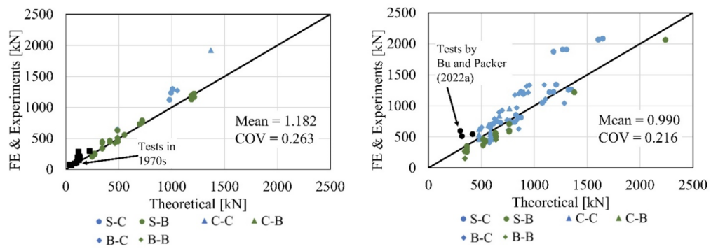
In total, 628 numerical analyses were considered and a reliability study was performed using a first-order reliability method, for all data groups, for eventual application to design. The FE results were compared with the connection nominal strengths predicted by AISC 360-22 and sample comparisons are shown in Figures 5 and 6, where both figures consider the results from balanced branch load case models, without hidden toe welds. Figure 5 includes a local yielding limit state for the chord member, but Figure 6 does not. It can be observed that the AISC 360-22 recommendations can predict the connection strength better if the limit state of chord member yielding (Figure 5) is considered. However, there are still a large number of data points in Figure 5 that fall below the line of unity (mostly the points with high Ov, where a branch shear limit state is not included), indicating that some improvement to the design equations (in AISC 360-22 Table K3.2) is also needed. The legends in Figures 5 and 6 are given in the format of “X-Y”, where X is the failure mode recorded from the FE analysis, and Y is the governing limit state in the design recommendation. The letters in the positions of X and Y represent the following: (i) S – branch shear failure; (ii) B – local yielding of branches; (iii) C – local yielding of chord.

Right image (a) Ov < 80%
Left image (b) Ov ≥ 80%

Left image (a) Ov < 80%
Right image (b) Ov ≥ 80%
Furthermore, FE results with imbalanced branch loading were also evaluated, to investigate whether the requirement for the hidden toe weld is valid. (At present, in AISC 360-22, the hidden toe needs to be welded if the difference in the branch force normal components is greater than 20%). It turns out that the performance of the design recommendations in AISC 360-22 for imbalanced loading cases is fairly consistent with that for balanced loading cases, with the hidden toe unwelded. Therefore, the requirement for hidden toe welds in significantly different branch loading cases can be lifted, for overlapped K-connections which have full-strength welds elsewhere.
Conclusions and Recommendations
Based on the overall FE parametric study and the laboratory experiments performed, the following conclusions and recommendations can be made for overlapped rectangular HSS K-connections, with respect to AISC 360-22 Chapter K. (In Bu and Packer (2023), design recommendations for other codes and guides (e.g., Eurocode 3 and CIDECT DG3) are also made).
- The existence of the hidden toe weld to the overlapped branch slightly increases the connection capacity (by a maximum of 12%), relative to the unwelded counterpart, and the branch load case also slightly affects the connection capacity (by a maximum of 6%). Thus, welding the hidden toe can be considered unnecessary for partial overlaps (Ov < 100%), but this is subject to: (i) having full-strength welds (which develop the yield strength of the connected branch wall) elsewhere; and (ii) the design provisions proposed below.
- With the hidden-toe-unwelded and the remaining welds developing the yield capacity of the branch walls, the connection capacity is not compromised by imbalanced branch loads. Therefore, the restriction in AISC 360 that hidden toe welds are required for connections with differences in branch load normal components greater than 20% may be lifted. Also, such connections under imbalanced branch loadings can be designed directly using the recommended K-connection limit states, without being separated into two equivalent connections (or free-body diagrams).
- The current design rules in AISC 360-22 Table K3.2 (based solely on the single limit state of local yielding of the branches) are inadequate because they do not provide a sufficient safety (or reliability) index of 3.0, particularly for overlaps of Ov ≥ 80% (see correlation in Figure 6). However, a suitable design procedure can be achieved by ignoring the potential for branch shear failure and checking just two limit states, as follows: (i) local yielding of the branches due to uneven load distribution (#4 below); and (ii) local yielding of the chord under combined axial load and bending moment (#5 below).
- Local Yielding of the Branches due to Uneven Load Distribution
It is recommended that Eqs. (K3-10), (K3-11) and (K3-12) be replaced by Eqs. (1) and (2):
- When 25% ≤ Ov < 50%,

- When 50% ≤ Ov ≤ 100%,

For available connection strength, φ = 1.00 (LRFD) for Ov < 100%, or φ = 0.95 for Ov ≥ 100%.
In the existing Eqs. (K3-10) to (K3-12), the branch capacity is calculated by adding the effective areas together as a boxed-shape branch, whereas in the proposed Eqs. (1) and (2) the branch capacity is calculated by subtracting the ineffective areas from the branch gross area. This is a more accurate method for branch effective area calculation, especially for thick-walled, cold-formed, HSS members where the corner radii can be quite large.
It is noted that the overlapped branch toe should be welded for overlaps of Ov ≥ 100%. This corresponds to a fully overlapped connection (Figure 1(b)), and in this instance the toe is not really hidden and the weld at that location also represents the heel weld for the overlapping branch to the chord. Overlaps of Ov > 100% are created if the overlapping branch rides slightly up the overlapped branch.
- Local Yielding of the Chord due to Combined Loading
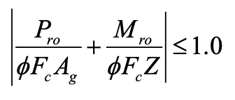
It is recommended that Eq. (3) be added to Table K3.2 as another requirement for overlapped K-connections:

Eq. (3) represents the chord utilization, or maximum normal stress ratio in the chord connecting face (tension or compression) on either side of the connection, due to the combined effect of chord axial load and bending. Mro is the bending moment in the chord, including the moment caused by the eccentricity of the horizontal components of the branch forces. The plastic moment capacity, based on Z, is used because most chord members are compact (but can be replaced by S if non-compact chord sections are used).
Eq. (3) is very similar to Eq. (K1-6) in Section K1.3 of AISC 360-22. Eq. (3) could be considered a member cross-section capacity check, rather than a connection capacity check, but it does serve as an upper limit on the branch loads. For available connection strength, φ = 1.00 (LRFD) for Ov < 100%, or φ = 0.95 for Ov ≥ 100%, in Eq. (3).
References
AISC. 2022. “Specification for Structural Steel Buildings”, ANSI/AISC 360-22, American Institute of Steel Construction, Chicago, IL.
Bu, X.D. and Packer, J.A. 2023. “Hidden Toe Welds in RHS-to-RHS Overlapped K-Connections”, Journal of Structural Engineering, American Society of Civil Engineers, Vol. 149, No. 3, 04022258-1 – 22.
CEN. 2021. “Eurocode 3: Design of Steel Structures – Part 1-8: Design of Joints”, prEN 1993-1-8:2021, European Committee for Standardization, Brussels, Belgium.
IIW. 2012. “Static Design Procedure for Welded Hollow Section Joints – Recommendations”, 3rd edition, IIW Doc. XV-1402-12, International Institute of Welding, Genoa, Italy.
ISO. 2013. “Static Design Procedure for Welded Hollow Section Joints – Recommendations”, ISO 14346, International Organization for Standardization, Geneva, Switzerland.
Packer, J.A., Wardenier, J., Zhao, X.-L., van der Vegte, G.J. and Kurobane, Y. 2009. “Design Guide for Rectangular Hollow Section (RHS) Joints under Predominantly Static Loading”, CIDECT Design Guide No. 3, 2nd edition, Comité International pour le Développement et l’Étude de la Construction Tubulaire, Geneva, Switzerland.
May 2023
Design Example: HSS Overlapped K-Connections With and Without the Hidden Toe Weld
A recent study has proven that the hidden toe of the overlapped HSS branch in rectangular K-connections does not need to be welded to achieve proper connection capacity. Step through an example demonstrating the process for designing an overlapped K-connection without the hidden toe weld.