Concrete-Filled Double-Skin Tubes
By Jeffrey A. Packer
Bahen/Tanenbaum Professor of Civil Engineering, University of Toronto, Ontario, Canada

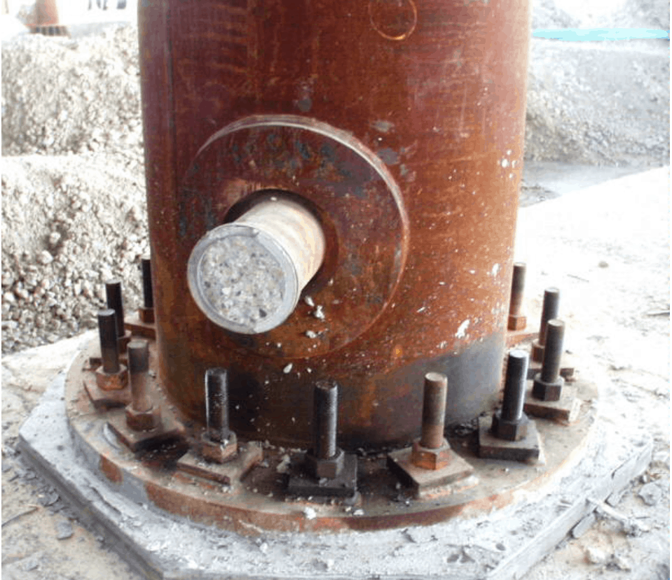
Most structural engineers are very familiar with the concrete-filled tube (CFT) concept, particularly for use as a composite column. The design of such compression members is well covered by AISC 360 Chapter I2.2 (AISC 2010). Small columns can be filled by placing the concrete into the HSS from above or, more commonly (especially for large hollow sections), pumping a self-consolidating concrete from the bottom (Figure 1). A non-shrink concrete or cementitious grout can be specified to ensure composite action. The advantages of filling a hollow section with concrete include: (i) increased column capacity; (ii) increased fire resistance; (iii) increased member stiffness (see Eqn. (I2-12) in AISC-360); (iv) a potential for increased connection capacity. Increased connection capacity (iv) may result if a limit state involving indentation of the hollow section controls connection design with an un-filled hollow section; the addition of a solid infill to the main tube member will then negate this failure mode.
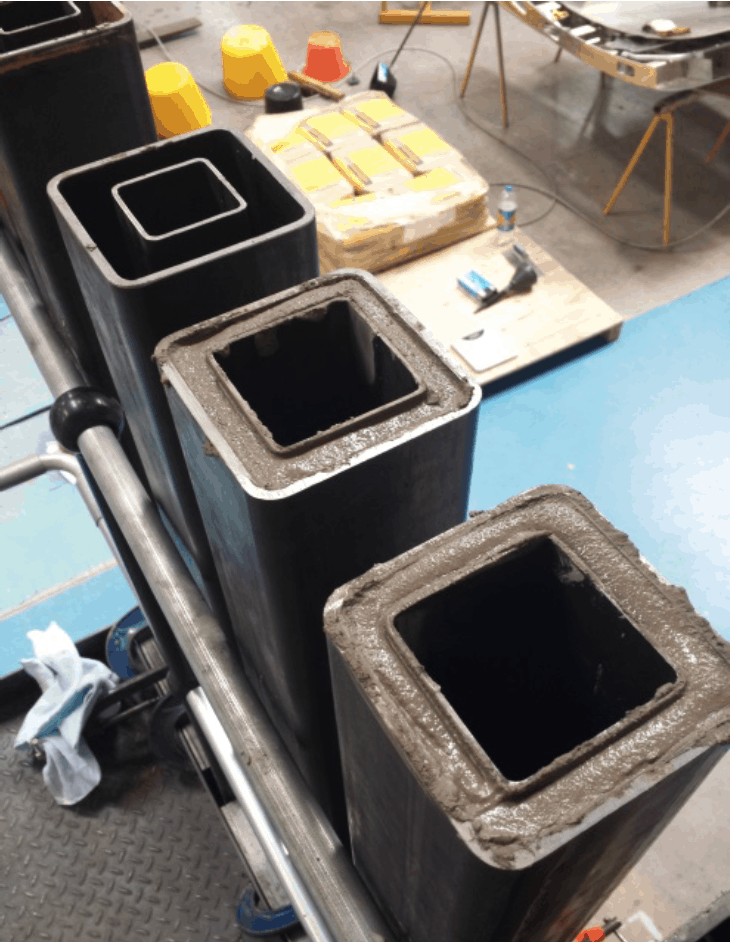
Recently, another form of composite hollow section has come to be used; the so-called concrete-filled double-skin tube (CFDST). Double skin composite construction, involving a steel-concrete-steel system, was originally used in tube tunnels; the sandwich cross section was shown to have a high bending stiffness that avoided instability under external pressure. The CFDST involves a tube-in-tube arrangement, where the steel sections can be round, square or rectangular hollow sections, with the annulus between the hollow sections filled with concrete (such as self-compacting) or grout. An HSS example of this is shown in Figure 2. The advantages of such a composite member have been cited as (Zhao and Han 2006):
(i) A lighter member weight compared to a hollow section fully filled with concrete, which offers advantages for building and foundation design;
(ii) Good cyclic performance, similar to a fully filled hollow section;
(iii) Good fire resistance due to the concrete infill, and protection of the inner tube;
(iv) High ductility, due to the composite cross section.
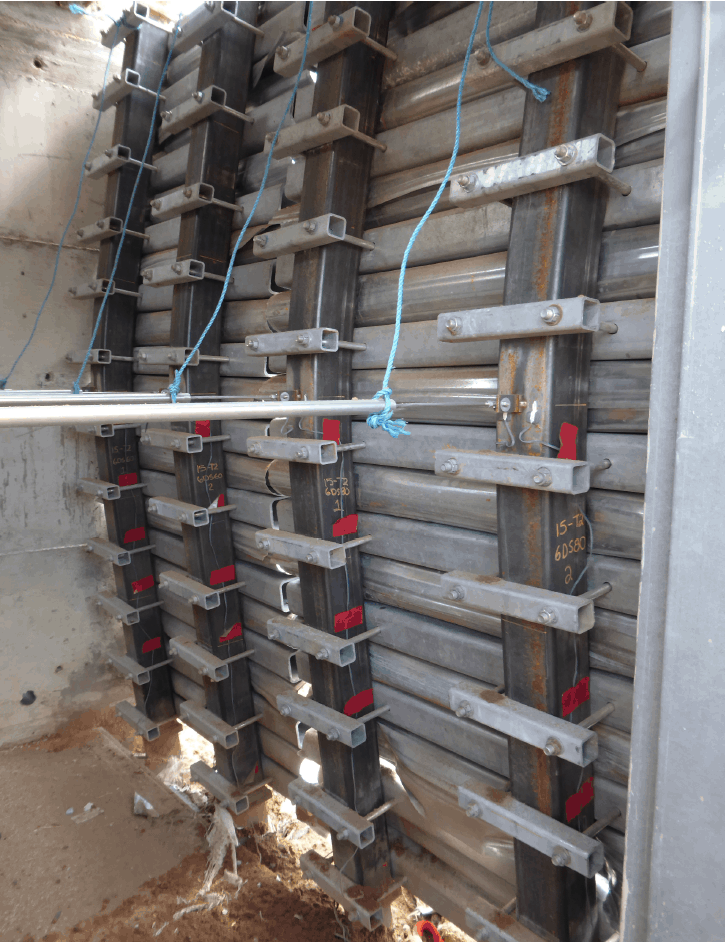
The CFDST thus represents an option for an all-purpose column or bridge pier, offering: good seismic performance (Han et al. 2006) with a relatively light member weight; good fire resistance that even exceeds tubular columns fully filled with concrete, because of the relatively low temperature in the inner steel tube (Yang and Han 2008); good lateral impact and blast behavior (Zhao et al. 2015), as illustrated in Figure 3.


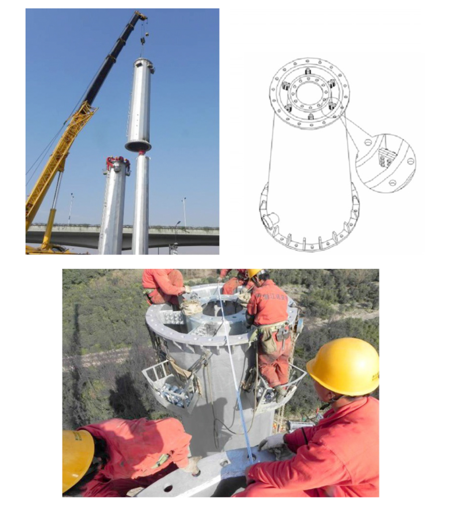
Figure 4 shows a recent CFDST application in China, using an inner tapered tube (1.2m maximum diameter) within an outer tapered tube (2.1m maximum diameter), to form a 220 kV electricity transmission line pole. In this case the CFDST member also avoided the use of thick steel plate for a steel-only, single-tube pole. During construction, the inner tube (per vertical segment) was erected first, followed by the outer tube (as shown in Figure 4). After erection, concrete was poured in the interlayer. The two hollow sections need to be carefully kept in their correct positions during construction of a CFDST and this will typically involve the use of steel spacers. Passage to the inner void also needs to be properly sealed off (typically at the bottom of the member) to avoid filling the entire assembly with concrete/grout. For typical HSS sizes the annulus to be filled will be relatively narrow, so a high-fluidity, non-shrink, cementitious grout can be specified.
As one might imagine, the outer tube of a CFDST behaves like a concrete-filled tube, with local buckling of the tube only being possible towards the outside, thus larger wall slenderness (D/t, B/t or H/t) values are permissible without the occurrence of elastic local buckling (relative to an unfilled hollow section); see AISC 360-10 Table I1.1A. Similarly, the inner tube is constrained to only buckle towards the inside. The cross-sectional capacity of a CFDST in axial compression can be estimated using the method of superposition; i.e., a sum of capacities of the outer tube, inner tube and the concrete (Zhao et al. 2010):
N CFDST = N Outer HSS + N Concrete + N Inner HSS
Equation 1
where the contributions of N Outer HSS, N Concrete and N Inner HSS can be combined in a manner analogous to AISC 360-10 Section I2.2 to obtain Pno. For compact steel sections, per AISC 360 Table I1.1A, Zhao et al. (2010) note that Pno is similar to Eqn. (I2-4).
From experimental research, Zhao et al. (2010) recommend that the ultimate moment capacity of the CFDST cross section in pure flexure be determined by:
M CFDST = M Outer HSS-with-concrete + M Inner HSS
Equation 2
where M Outer HSS-with-concrete is the moment capacity of the outer HSS with the concrete infill, for a plastic stress distribution, assuming a compact outer HSS per AISC 360 Table I1.1B.
Notation
| B | = external width of square or rectangular HSS |
| D | = external diameter of round HSS |
| H | = external depth of square or rectangular HSS |
| M CFDST | = ultimate moment capacity of CFDST in bending |
| N CFDST | = capacity of CFDST cross section in axial compression |
| Pno | = nominal compressive strength of zero length, doubly symmetric, axially loaded composite member (AISC 360) |
| t | = design wall thickness of HSS |
References
AISC. 2010. “Specification for Structural Steel Buildings”, ANSI/AISC 360-‐10, American Institute of Steel Construction, Chicago, IL, USA.
Han, L.-H., Huang, H., Tao, Z. and Zhao, X.-‐L. 2006. “Concrete-Filled Double Skin Steel Tubular (CFDST) Beam-Columns subjected to Cyclic Bending”, Engineering Structures, Vol. 28, pp. 1698-‐1714.
Li, W., Ren, Q.X., Han L.-H. and Zhao, X.-L. 2012. “Behaviour of Tapered Concrete-Filled Double Skin Steel Tubular (CFDST) Stub Columns”, Thin-Walled Structures, Vol. 57, pp. 37-48.
Yang, Y.F. and Han, L.-H. 2008. “Concrete-Filled Double-Skin Tubular Columns under Fire”, Magazine of Concrete Research, Vol. 60, No. 3, pp. 211-‐222.
Zhao, X.-L. and Han, L.-H. 2006. “Double Skin Composite Construction”, Progress in Structural Engineering and Materials, Vol. 8, pp. 93-102.
Zhao, X.-L., Han, L.-H. and Lu, H. 2010. “Concrete-Filled Tubular Members and Connections”, Spon Press, Taylor & Francis Group, UK, ISBN 978-0-415-43500-0.
Zhao, X.-L., Ritchie, C.B. and Packer, J.A. 2015. “Status Report on the Dynamic Material Performance of Cold-Formed Hollow Sections”, CIDECT Report 16G–6/15, Monash University, Australia and University of Toronto, Canada.
October 2015