Review of AISC Design Guide No. 24 – 2nd Edition
By Jeffrey A. Packer
Professor, Department of Civil & Mineral Engineering, University of Toronto, Ontario, Canada
July, 2024
The ultimate HSS Users’ Manual has now been issued. This is Design Guide No. 24 on “Hollow Structural Section Connections”, published by the American Institute of Steel Construction (AISC). A second edition, released in March 2024 in both digital and hard-copy formats, has replaced the 2010 first edition.
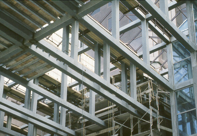
No-one can disagree that exposed HSS are aesthetically appealing and ideal for free-form architectural expression (see Figure 1), but they are optimal for many structural applications too – columns, bracings, trusses, and large-span roofs especially. However, connections to HSS have proved problematical relative to open steel sections. This guide hopefully goes a long way towards alleviating the concerns of designers.

2nd Edition vs. 1st Edition
A comparison of the 2nd edition of DG 24 (Packer and Olson, 2024) to the 1st edition (Packer et al., 2010) is useful. As one can see in Table 1, it is more than twice the size. There is a lot more explanation and guidance, more connection types are covered, and there are many more design examples. Significantly, it is right up-to-date with the current AISC Specification (AISC, 2022) and the 16th edition Manual (AISC, 2023). As with the 1st edition, the scope of the new design guide pertains to predominantly static loading. Users will find that the gaps between AISC 360-22 Chapters J & K, and the Manual – and their application to HSS connections – are now filled in.
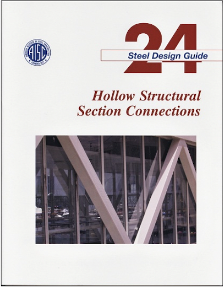 by Jeffrey Packer, Don Sherman & Maura Lecce | 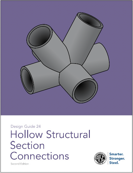 by Jeffrey Packer & Kim Olson |
|
|
Contents by Chapter
Chapter 1 – Introduction
This starts with inspiring applications, illustrates current HSS manufacturing methods, and reviews the important features of tubular product standards (ASTM A500, A1085, A1065, A847, A53, A501, A618, A1110, A1112; API 5L; CSA G40). The advantages of HSS are pointed out with regard to: AESS, torsion, compression, surface area, concrete filling, resistance to fluid flow, cold and hot bending, and connecting to castings. Some issues that arise with HSS, such as galvanizing and metalizing, notch toughness, internal corrosion and freezing, and fire protection, are discussed.
Even at this stage of the book, the essential principles of HSS connection design are identified; in order to avoid reinforcing connections (which is costly and even disallowed architecturally in many cases), connection design and fabrication criteria must be integrated with structural modeling and member selection. To maximize the strength and stiffness of HSS connections, the through member – the chord in a truss-type connection or the column in a beam-to-column or bracing-to-column connection – should be relatively thick. Conversely, the branch member in an HSS-to-HSS welded connection should be relatively thin and wide but, for fabrication purposes, still have the ability to sit on the “flat” of the chord member if using rectangular HSS.
Chapter 2 – Limit States for HSS Connections
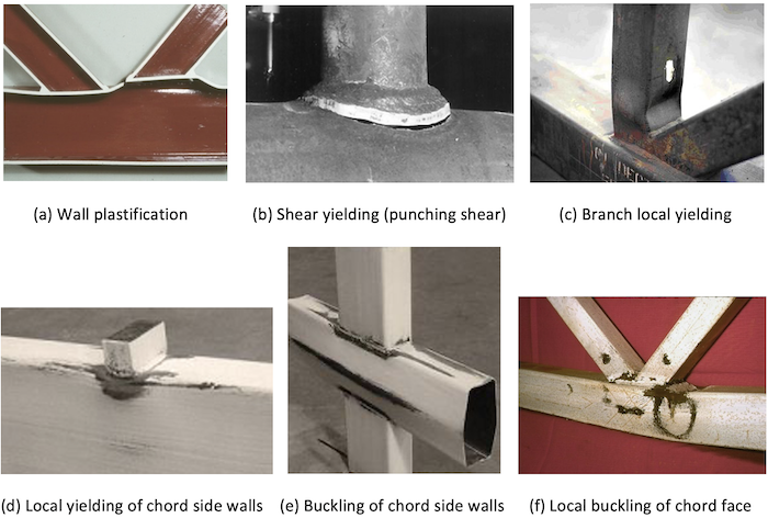
This new chapter is the focus and emphasis of the Design Guide, where the link between each connection failure mode and its limit state design formula is made. The 10 potential failure modes of: chord wall plastification, chord shear yielding (punching shear), branch local yielding due to uneven load distribution, local yielding of chord side walls, local crippling of chord side walls, buckling of chord side walls, shearing of the chord cross section, local buckling of the chord connecting face, shear yielding of overlapped branches, and chord distortional failure, are covered in detail, with an explanation of how connection “ultimate strength” is determined. Some of these failure modes are illustrated in Figure 2.
Chapter 3 – Welding
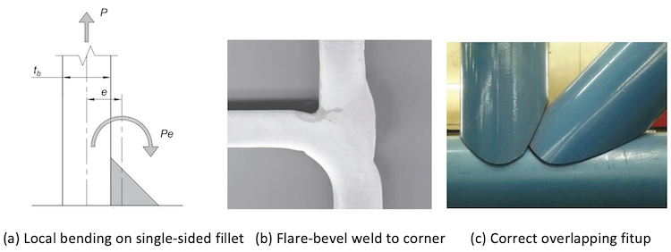
Aspects of welded fabrication that are especially important for HSS construction are discussed. Two weld design philosophies are permissible: (i) design for actual forces in members, in conjunction with weld effective lengths (described in detail); or (ii) design to develop the yield capacity of the attached branch wall. Fillet welds are inherently single-sided to a branch member wall so, when that wall pertains to a rectangular HSS and it is loaded in tension, the directional-strength-increase factor (kds) cannot be used. This is because the tension force tends to open the weld joint at the root, as shown in Figure 3(a). PJP flare-bevel and flare-V groove welds commonly occur when welding in HSS corner regions (Figure 3(b)). The importance of HSS end profiling and beveling is stressed, along with the correct sequence of member overlapping or layup where at least one branch attaches fully to a “through member” (Figure 3(c)). The chapter concludes with five weld design examples: (i) skewed fillet weld; (ii) fillet weld size in a shear connection; (iii) transverse weld to a rectangular HSS; (iv) welds to a rectangular HSS overlapped K-connection using effective lengths; and (v) welds to a rectangular HSS overlapped K-connection to develop branch capacity.
Chapter 4 – Mechanical Fasteners and Bolted Joints
Methods for fastening to an HSS closed section are covered herein. Most limit states for bolted HSS connections are common to all bolted connections, but some differences (to the classic T-stub model) occur for prying action and some additional HSS limit states need to be considered (HSS wall plastification, and fastener pull-out in tension). The fastening methods covered include: through bolts, blind bolts, threaded studs, powder-actuated fasteners (e.g. by Hilti) and screws – all of which avoid the need for placement of a nut inside the hollow section – and structural nut holders (Figure 4). The latter allow regular high-strength ASTM bolts from one side. Three design examples cover: (i) through-bolt connection in shear; (ii) threaded stud-to-HSS connection in tension; and (iii) bolted WT-to-HSS connection in tension.

Chapter 5 – Shear Connections
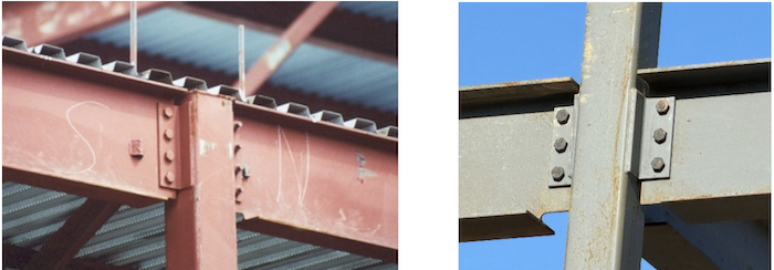
By definition, these are beam-to-column connections where the joint between the members is not required to transfer moment but allows for rotation associated with the member behavior under its applied loads. Seven wide-flange beam-to-HSS column connection types are described, in an order from least expensive to most expensive, starting with the popular single-plate (also known as shear tab) connection (for which there is a design example). This is followed by the: single-angle connection (as shown in Figure 5); double-angle connection (with a design example); WT connection; unstiffened seat connection; stiffened seat connection; and through-plate connection (with a design example).
Chapter 6 – Moment Connections
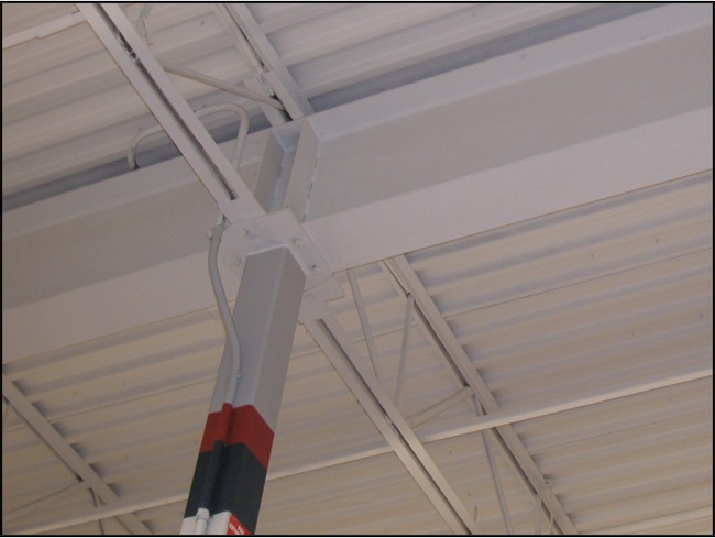
Six different options for wide-flange beam-to-HSS moment connections are described, most of which classify as fully restrained (FR). The simplest and most inexpensive option for a one-story building is a continuous beam over the HSS column, which is very popular for “big box stores” (Figure 6). Other FR options presented are: the external diaphragm (cut-out) plate connection; welded Tee connection; through-plate connection; and internal diaphragm plate connection. The directly welded beam-to-HSS column connection (which can be reduced to two transverse plate connections by considering just the flanges) is also included, but this normally only qualifies as a partially restrained (PR) connection. Design examples are given for all connection types except the internal diaphragm plate connection.
Chapter 7 – Tension and Compression Connections
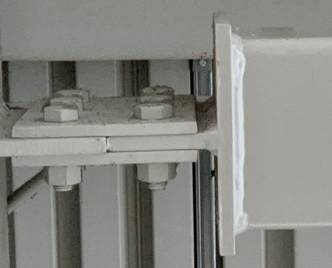
This chapter deals with welded and bolted connections to the ends of HSS members, under predominantly axial loading. The most common application of such connections is with bracing members in braced frames. Six common end connections to HSS members are presented, of which three – the end Tee connection (Figure 7), the slotted HSS-to-gusset plate connection, and the sandwich (or side) gusset-plated connection – are unique because they cause shear lag in the HSS member due to non-uniform loading on the member end. The end Tee connection and the slotted HSS connection are, moreover, prone to buckling of the gusset plate/stem under compression loading, so a design approach for this plate instability failure mode is also given. The remaining three connections are all bolted end-plate connections under axial tension: to round HSS with the bolts uniformly spaced around the tube; to rectangular HSS with bolts on just two sides of the HSS; and to rectangular HSS with bolts on all sides of the HSS. Four design examples are given for: a Tee connection in both tension and compression; a slotted HSS-to-gusset plate connection in tension; an end plate-to-round HSS connection in tension; and an end plate-to-rectangular HSS connection with bolts on all four sides, loaded in tension.
Chapter 8 – Line Loads and Concentrated Forces on HSS
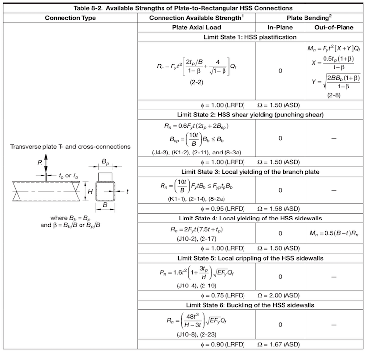
Plates, welded transversely or longitudinally to the wall of an HSS member, form the topic of this chapter. For both plate-to-round, and plate-to-rectangular HSS, the connection types covered are: transverse branch plate T- and cross-connections; longitudinal branch plate T-, Y- and cross-connections; transverse through-plate connections; and longitudinal through-plate T- and Y-connections. Two possible limit states are presented for plate-to-round HSS connections, whereas six are used for plate-to-rectangular HSS connections (Table 2). For both round and rectangular HSS cases, comprehensive available strength tables are given in a format based on connection type, an example of which is shown in Table 2. This supplements the partial coverage of plates-to-HSS in Section K2 of AISC 360-22. The relevant limits of applicability are now given for each limit state design equation, rather than as two collective groups (for plate-to-round HSS and plate-to-rectangular HSS). Three design examples round out the chapter, for: a longitudinal branch-plate and through-plate connection to a rectangular HSS; a transverse branch-plate connection to a rectangular HSS; and a wide-flange beam-to-round HSS column moment connection.
Chapter 9 – HSS-to-HSS Truss Connections
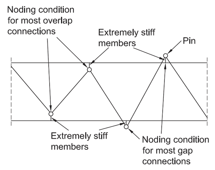
This the longest chapter at 58 pages; it concentrates on the special case of welded truss-type connections between two or more HSS members, where the branches are subjected to predominantly axial loading. Relying on the elaboration of limit states described in Chapter 2, the chapter probes: connection parameters and layouts, how to classify connections (into types such as K, Y or cross), appropriate truss modeling for the service and ultimate limit states (per Figure 8), round HSS webs-to-rectangular HSS chord members, KT-connections (with three web members), and multi-planar HSS members. Connection available strengths, and their corresponding limits of applicability, are tabulated in a similar manner to Chapter 8 – by listing and numbering every limit state, for each connection type. Six design examples round out the chapter: two for round HSS (a Y-connection; and an overlapped K-connection) and four for rectangular HSS (a cross-connection; an overlapped K-connection; a gapped K-connection, with unbalanced branch loads; and an overlapped KT-connection).
Chapter 10 – HSS-to-HSS Moment Connections
The final chapter expands on AISC 360-22 Section K4 and Chapter J, covering planar connections between round or rectangular HSS members in the shape of a T-, Y- or cross-connections. Branches can have in-plane or out-of-plane moment loading (unlike truss-type connections where the branches have axial loading). A common application is in 2D or 3D frames, hence the requirements for HSS Vierendeel frames (Figure 9) are pointed out. The limit states for HSS moment connections largely follow those for their axially loaded counterparts (in Chapter 9). Connection available strengths, and their corresponding limits of applicability, are tabulated in a similar manner to Chapters 8 and 9. Four design examples are given for: a round HSS cross-connection under branch in-plane bending; a rectangular HSS T- or Vierendeel connection under in-plane bending; a rectangular HSS cross-connection under branch out-of-plane bending; and a rectangular HSS T-connection under branch out-of-plane bending.
References
AISC. 2022. “Specification for Structural Steel Buildings”, ANSI/AISC 360–22, American Institute of Steel Construction, Chicago, IL.
AISC. 2023. “Steel Construction Manual”, 16th edition, American Institute of Steel Construction, Chicago, IL.
Packer, J.A., Sherman, D. and Lecce, M. 2010. “Hollow Structural Section Connections”, Steel Design Guide No. 24, 1st edition, American Institute of Steel Construction, Chicago, IL.
Packer, J.A. and Olson, K. 2024. “Hollow Structural Section Connections”, Steel Design Guide No. 24, 2nd edition, American Institute of Steel Construction, Chicago, IL.
STI Limit State Tables Per AISC 360
STI's free Limit State Tables have been updated to the AISC 360-22 Specification and 16th Edition Manual. These tables serve as a comprehensive guide to the HSS limit state checks required for a wide range of HSS connection conditions and loading scenarios, including shear, axial, moment and truss connections. This invaluable resource also serves as an excellent companion to STI's Spreadsheet Design Tools.