Filling the Void: A Central Resource for Designing Concrete Filled HSS Columns
By Mike Manor, PE, MLSE
Technical Consultant, Steel Tube Institute
June, 2024

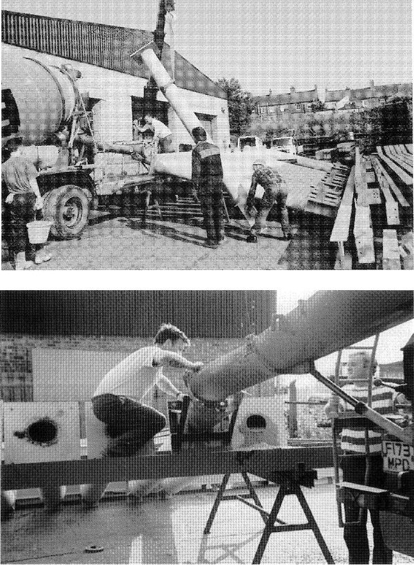
Photo Credit: CIDECT Design Guide 5
Concrete and steel are two of the most versatile building materials, but when they combine forces, even greater gains can materialize. HSS columns work efficiently to carry high loads without taking up much space. However, regardless of the size, inside is just wasted space, so why not fill it with concrete? Combining the materials creates an optimal blend through the synergistic effect of the steel, confining the concrete, while the concrete decreases the slenderness of the HSS, increasing the local buckling stability by bracing the sidewalls. However, understanding the behavior, knowing how to design, and understanding the logistics for installation in the field all require some research. This article will serve as a central information hub by providing a brief overview of concrete filled HSS columns.
Specifically, this article will touch upon the following aspects of HSS composite column design:
- Design Example
- Column Capacities with 4ksi and 6ksi NW Concrete
- High Strength Steel and/or High Strength Concrete
- Further Insights into Composite Member Design
- Connecting to Composite HSS Columns
- Fire Rating
- Logistical Considerations
1. Design Example
Given:
- ASTM A500 Gr. C (Fy = 50ksi)
- HSS 14x14x3/8
- Unreinforced Fill: f’c = 6ksi
- Normal Weight Concrete: wc = 145pcf
- Lc = KL = 42’
HSS Geometry [AISC 16th Manual Table 1-12]
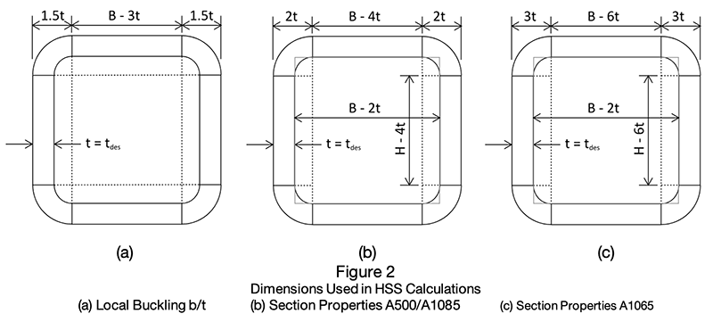
The following corner radius assumptions apply when calculating geometric properties for HSS(see Figure 2).
- corner radius= 1.5tdesign when determining b/t and h/t ratios
- corner radius= 2.25tdesign when determining workable flat width and depth
- corner radius= 2tdesign for A500 and A1085 when determining all other section properties including Ac, Sx, Sxc, Ix, and Ixc
- corner radius= 3tdesign for A1065 when determining all other section properties including Ac, Sx, Sxc, Ix, and Ixc

B = nominal HSS width
H = nominal HSS height
b = width of HSS flat (varies depending on the calculation being performed)
h = height of HSS flat (varies depending on the calculation being performed)
workable flat = reasonable HSS flat distance for detailing connections
tnom = nominal HSS thickness
tdes = HSS design thickness for ASTM A500 = 0.93tnom
tdes = HSS design thickness for ASTM A1085 and A1065 = tnom
λ = width-to-thickness slenderness ratio
B = H = 14 in
tnom = 0.375 in
tdes = 0.349 in
b = h = B – 3tdes = 14 in – 3 x 0.349 in = 12.953 in
λ = b/tdes = 12.953/0.349 = 37.1
Area of Steel As = 18.7in2
Area of Concrete Ac = (B – 2tdes)2 – (tdes)2(4 – π) = 176.8in2
Calculated by starting with a concrete square and subtracting the area
outside each corner radius as shown in Figure 2b
Total Area Ag = 18.7in2 + 176.8in2 = 195.5in2
Steel Moment of Inertia Is = 577in4
Concrete Moment of Inertia Ic = 2605in4
Calculated by breaking up the concrete area into one large
rectangle, two small rectangles, and four quarter circles as shown in Figure 2b

Composite Section Limitations [AISC 360-22 I1.3 & I2.2a]
Specified Yield Strength Fy = 50ksi ≤ 75ksi OK
Specified Concrete Strength 3ksi ≤ f‘c = 6ksi ≤ 10ksi OK
Steel Cross-Sectional Area As = 18.7in2 ≥ 0.01Ag = 1.96in2 OK
Rebar Reinforcement* Asr = 0in2 OK
*(no required minimum)
Slenderness Check
Compression λ = 37.1 (see above)
λr = non-compact element width-to-thickness limit
λp = compact element width-to-thickness limit

Strength Determination
For calculating the strength of a composite column, AISC 360-22 Chapter I provides four different analysis options. The first method is called the plastic stress distribution method, which is the most general case and easiest to calculate, but it is limited to compact sections. Since nearly all filled HSS sections are compact, this method is most often used and has been selected for demonstration in this example.
Filled Composite Axial Capacity [AISC 360-22 I2.1b & I2.2b]
C2 = geometric coefficient for the assumed concrete compressive stress in the plastic stress distribution method for composite members
C3 = coefficient for the effective rigidity calculation of filled composite compression members
Rectangular section: C2 = 0.85
Note: For round HSS, C2 = 0.95 due to increased confinement

Pno = nominal axial compressive strength without consideration of length effects
Pn = nominal compressive axial strength
Pe = elastic critical buckling load
Pp = plastic axial compressive strength

2. Column Capacities with 4ksi and 6ksi NW Concrete
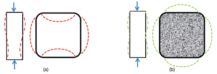
Hollow HSS versus filled HSS can have a substantial difference in axial strength capacity. The concrete greatly affects the stiffness, strength, and ductility of the steel in the composite section. As shown above in equations I2-2, I2-4, and I2-12, the effective stiffness of the composite section increases and thus the global Pe and Pn values get larger as well. At the local level, Figure 3 demonstrates a comparison of the compressive buckling behavior of HSS both with and without concrete fill. To punctuate the difference, the allowable b/t ratio limits drastically change when comparing AISC 360-22 Tables B4.1a (unfilled HSS = 1.40 rectangular slenderness coefficient) and I1.1a (filled HSS = 2.26 rectangular compactness coefficient), meaning that many slender HSS columns become compact when filled with concrete. The reality is that almost all ASTM A500 Grade C HSS sizes are considered compact for composite members. AISC 360-22 Section I1.4 has a user note that provides guidance on which member sizes fit into the composite compact designation and lists the handful that do not.

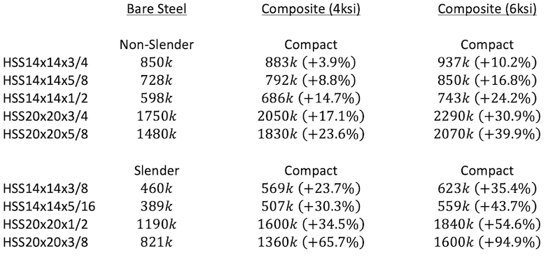
Below is a table that highlights the composite capacity of various HSS sizes, with both 4ksi and 6ksi normal weight concrete fill, with the 42-foot unbraced length from the example above. The percentages listed demonstrate the increase in axial capacity compared to bare steel HSS as a baseline. Note that the effects of the concrete fill increase as the area of steel decreases.

Fortunately, the axial capacity calculation steps have already been tabulated by both STI and AISC covering various conditions. STI HSS Design Manual Volume 2A (link) has capacity tables 2.2-3 through 2.2-8 for HSS round, square, and rectangular HSS including A500, A1085, and A1065 filled with f‘c = 4ksi concrete up to a maximum unbraced length Lc = 65ft. Additionally, STI Professional Members have access to a spreadsheet at this link that performs calculations for any HSS size, unbraced length, and concrete strength within the limits listed in the next section. AISC 360-22 has filled HSS composite design tables in volume 2 of the companion to the 16th Edition Steel Manual. Tables 4-A through 4-F cover filled round, square, and rectangular HSS for A500 Gr. C Fy = 50ksi filled with concrete strengths of f‘c = 4ksi and 5ksi up to a maximum unbraced length Lc = 40ft. The manual companion can be found on AISC’s website at this link.
3. High-Strength Steel and/or High Strength Concrete
In the AISC 360-22 Specification, Appendix 2 has been revised to cover the design of rectangular filled composite members with higher-strength materials than what is covered by Chapter I of the Specification. This appendix accommodates increased strength for the HSS steel, the concrete fill, or both. Following is a chart showing the limits of applicability for each specification section.

Longitudinal reinforcement (rebar) is not required but can be used. However, the effect of the reinforcement is ignored in the available strength calculation. For axial compression, the capacity calculation is almost entirely the same as the regular-strength counterpart with one main exception. The axial nominal compressive strength without consideration of length effects, Pno, has a revised equation in the appendix based on the critical buckling stress of the composite section. The Appendix 2 commentary references the two main research papers listed below that the Appendix 2 provisions are based on, which provide additional discussion on the revised procedure. For more information on high strength steel, AISC has a report available from the ad hoc task group on its website (link).
Alghossoon, A.M. and Varma, A.H. (2020), “Interaction of Section and and Member Slenderness on Behavior and Design of Rectangular High Strength Concrete Filled Tube Members,” Bowen Laboratory Research Report, Purdue University, West Lafayette, Ind. (Link)
Lai, Z. and Varma, A.H. (2018), “High-Strength Rectangular CFT Members: Database, Modeling, and Design of Short Columns,” Journal of Structural Engineering, ASCE, Vol. 144, No. 5, pp. 04018036-1-04018036-18. (Link)
4. Further Insights into Composite Member Design
The example in Part 1 above highlights the main design procedure for calculating the capacity of compact filled HSS members for axial loads with the plastic stress distribution design method. But what about non-compact or slender composite columns, or flexural design?
Slender or Non-compact Shapes
When composite members are slender or non-compact, AISC 360-22 Section I1.2 and commentary provides three design options: Strain Compatibility Method, Elastic Stress Distribution Method, and Effective Stress-Strain Method. Each section describes the procedure and applicability of each method.
Flexural Design and Force Interaction
Flexural members are covered in section I3.4 and have the same four analysis methods as for columns. Finally, force interaction is covered by section I5. Note that when using high-strength materials, the interaction of axial and flexural forces in section I5 must be modified per appendix section 2.4.
For more in-depth information on these topics, please refer to the following resource available on the STI website. ”Composite Concrete Filled HSS: Design Considerations” (link).
5. Connecting to Composite HSS Columns
Another important topic is connections to composite HSS members. Due to the synergistic effect of the steel and concrete working together, it is not enough to simply connect to the HSS steel member as is normally done. A portion of the load must transfer from the steel to the concrete to properly take advantage of the composite strength. Be aware that steel thickness is a factor in the connection capacity. Thus, it is recommended to consider the connections when selecting the HSS section to prevent issues with connection capacities down the line. A balance must be reached between column efficiency and connection requirements. Thus, the next referral is “Composite Column Connections” (link), which steps through the design concepts for ensuring the connection forces are properly transferred to the entire composite section.
6. Fire Rating
Composite columns offer a significant advantage with their inherent fire-resistant properties. Based on research, ratings up to three hours can be achieved without the need for any external fire resistance. When using the concrete fill to achieve fire ratings, internal concrete reinforcement should be used since the HSS will shed load into the concrete core as the temperature rises. Thus, in a fire event, the concrete core must eventually support the load by itself. For additional information and a list of resources, see the STI article called “Keeping Your Cool: How To Get Started With HSS Fire Ratings” (link).
7. Logistical Considerations
Finally, this article has been focusing entirely on engineering design up to this point. However, there are many logistical considerations for making a successful project. Some of these items include type of concrete to use, concrete installation methods, detailing requirements, constructability and more. For further discussion on this, refer to the STI article ”Practical Guidance for Concrete Filled HSS Columns” (link).
Conclusion
HSS columns are efficient members with many benefits. One unique benefit is the convenient hole in the middle that is perfect for filling with concrete to reap additional rewards such as increased strength and fire ratings without the need for additional materials for installation. Whether the intent is to reduce the column footprint or maximize height limits, composite HSS columns offer a significant boost to the positive impact of HSS. A wealth of information is available to grasp the full scope of capabilities and nuances of composite design. Recognizing that this topic could fill volumes, STI offers a companion resource that compiles all these resources into one convenient quick reference guide, which can be found on the STI website at this link.
HSS Reference Guide No. 1: Composite HSS
A wealth of information is available to grasp the full scope of capabilities and nuances of composite HSS design. Recognizing that this topic could fill volumes, STI offers a companion resource that compiles all these resources, encompassing member design, connections and fire resistance, into one convenient Reference Guide.