Design of Fillet Welds to Rectangular HSS
By Jeffrey A. Packer
Bahen/Tanenbaum Professor of Civil Engineering, University of Toronto, Ontario, Canada
Min Sun
Postdoctoral Fellow, Department of Civil Engineering, University of Toronto, Ontario, Canada
For HSS connections, current codes, standards, specifications and design guides (Wardenier et al., 2008; Packer et al., 2009; Packer et al., 2010; ISO, 2013) acknowledge two design philosophies for fillet weld design: (i) the weld can be proportioned so that it develops the yield strength of the connected HSS branch member; (ii) the weld can be proportioned so that it resists the actual forces in the connected HSS branch member.
Method (i) will produce an upper limit on the required weld size. Hence, it may be excessively conservative when the branch forces are low relative to the branch member capacity. Method (ii) involves a consideration of the effective length of the weld group. It generally allows for weld “downsizing” and hence is popular. AISC 360 (AISC, 2010) has adopted Method (ii) in Section K (Table K4.1) for welded connections to rectangular HSS by specifying various weld effective lengths, le, for different connection types and loading situations. Details of the two methods can be found in an earlier technical paper “Welding of Hollow Structural Sections”. As a sequel, this paper discusses the special considerations for the application of Chapters J and K in AISC 360 to the design of fillet welds to rectangular HSS.
Effect of loading angle on fillet weld strength
The fillet weld design clauses in AISC 360 Section J2.4(a) permit the use of a so-called “directional strength enhancement factor” for fillet welds (i.e. the “1.00 + 0.50sin1.5θ” term in Equation J2-5), which enables the weld strength to be enhanced when the direction of loading is non-parallel to the axis of the weld. The adoption of the directional strength enhancement factor, or “sinθ factor” into AISC 360 was based on experimental research on lap-splice connections where the connection was loaded in shear (Miazga and Kennedy, 1989; Lesik and Kennedy, 1990). It was found that the strength of the fillet welds tested gradually increased to 1.5 times as the loading angle increased from 0˚ (longitudinally loaded weld) to 90˚ (transversely loaded weld). However, AISC 360 does not permit the use of the “sinθ factor” when the “effective length method” of AISC 360 Chapter K is used for proportioning fillet welds in HSS connections (AISC 360 Commentary on K4) for the following reasons:

- Unlike lap-splice connections, fillet welds in many HSS connections have the welded attachment loaded in tension or bending, rather than in shear.
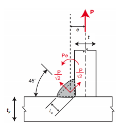
- Since welding can only be performed on one side of the hollow section wall, fillet welds to HSS members will be subject to a local eccentricity. For example, tension loading in an attached wall will produce additional tensile stress at the root of the weld (see Figure 1). In fact, North American codes and standards recognize that eccentric loading on a fillet weld, causing tension at the weld root, may reduce weld capacity. For example, CSA W59 (CSA, 2013) Clause 4.1.3.3.2 states that … “Single fillet and single partial joint penetration groove welds shall not be subjected to bending about the longitudinal axis of the weld if it produces tension at the root of the weld”. AWS D1.1 Section 2.6.2 (AWS, 2010) states that, in the design of welded joints, the calculated stresses shall include those due to eccentricity caused by alignment of the connected parts, size and type of welds, although this Section does pertain to connections which are “non-tubular”.
- It has been shown experimentally that the inclusion of the “sinθ factor” in the strength calculation is generally unsafe, when applied to rectangular HSS-to-HSS fillet-welded connections and used in conjunction with current AISC 360 Chapter K weld effective lengths/properties, because target structural reliability levels are not achieved (Packer and Sun, 2011; McFadden et al., 2013; McFadden and Packer, 2014; Tousignant and Packer, 2014).
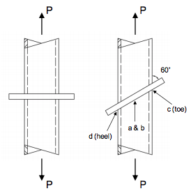
Furthermore, according to a recent experimental study (Packer et al., 2015) on behavior of fillet-welded connections between HSS and rigid end-plates (see Figure 2), where all of the weld length would be effective (i.e. the AISC “effective length method” is not applicable), by comparing the experimentally obtained weld strengths to the predicted nominal strengths per AISC 360, it was found that:

- Strength calculation including the directional strength enhancement factor leads to predictions which do not have a sufficient safety margin. Hence, restrictions do need to be placed on the application of such a directional strength enhancement factor for fillet welds in HSS connections, regardless of the connection type (e.g. HSS-to-HSS connection or HSS-to-plate connection). Thus, the nominal stress of the weld metal should be calculated as Fnw = 0.60FEXX per Table J2.5.
- When the directional strength enhancement factor is not included in the strength calculation of fillet welds to HSS, the equations in AISC 360 can be used with adequate safety level being achieved.
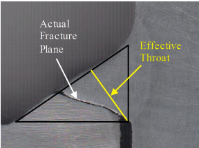
- In general, the actual fracture plane of the weld tested is closer to the HSS fusion face (see Figure 3) and has a longer failure line. Hence, it is conservative to use the weld “effective throat thickness” as defined by AISC 360 (i.e. the minimum distance between the root of the fillet weld and the face of the triangular weld profile) in strength calculations.

Interaction between fillet welds with different loading angles
As a special application of Section J2.4(a), which is for a linear weld group (i.e. all weld elements are in a line or are parallel, hence having the same deformation capacity under the applied load), Section J2.4(c) gives provisions for concentrically loaded connection with fillet weld elements of multiple orientations (longitudinal and transverse to the direction of applied load). It specifies that the nominal strength (Rnw) of concentrically loaded joints with both longitudinal and transverse fillet welds be determined as the greater of Equations J2-10a and J2-10b.
Rnw = Rnwl+Rnwt
(J2-10a)
Rnw = 0.85Rnwl+1.5Rnwt
(J2-10b)
This provision, which accounts for the deformation difference between longitudinal and transverse fillet welds in a weld group, was developed based on tests on lap-splice connections with multiple weld segments of different orientations (Callele et al., 2009). As a result of deformation incompatibility, the transverse weld prevents the longitudinal weld from reaching its full capacity before failure of the joint takes place. Hence, the tested weld groups possessed capacities considerably lower than the sum of the individual weld segment strengths. Callele et al. (2009) thus proposed a simple method to account for this phenomenon conservatively by reducing the capacities of the more ductile welds by 0 to 15%. For example, for a weld group containing longitudinal and transverse welds, the longitudinal weld can only develop 85% of its full capacity before joint failure, which is reflected in Equation J2-10b.
Notation
e = eccentricity
FEXX = Filler metal classification strength
Fnw = nominal stress of weld metal
le = effective weld length
P = applied force
Rnw = nominal strength of welded joint
Rnwl = total nominal strength of longitudinally loaded fillet welds
Rnwt = total nominal strength of transversely loaded fillet welds (without “sin θ” factor applied)
t = wall thickness of RHS branch
tp = thickness of intermediate plate
tw = effective throat thickness of weld
θ = angle of loading measured from the weld longitudinal axis for fillet weld strength calculation (in degrees)
References
AISC. 2010. “Specification for Structural Steel Buildings”, ANSI/AISC 360-10, American Institute of Steel Construction, Chicago, IL, USA.
AWS. 2010. “Structural Welding Code – Steel, 22nd edition”, ANSI/AWS D1.1/D1.1M:2010, American Welding Society, Miami, FL, USA.
Callele, L. J., Driver, R. G. and Grondin, G. Y. 2009. “Design and Behavior of Multi-Orientation Fillet Weld Connections”, AISC Engineering Journal, Vol. 46, No. 4, pp. 257-272.
CSA. 2013. “Welded Steel Construction (Metal Arc Welding)”, CSA W59-13, Canadian Standards Association, Toronto, Canada.
ISO. 2013. “Static Design Procedure for Welded Hollow Section Joints – Recommendations”, ISO 14346:2013 (E), International Organization for Standardization, Geneva, Switzerland.
Lesik, D. F. and Kennedy, D. J. 1990. “Ultimate Strength of Fillet Welded Connections Loaded in Plane”, Canadian Journal of Civil Engineering, Vol. 17, No. 1, pp. 55-67.
McFadden, M. R., Sun, M. and Packer, J. A. 2013. “Weld Design and Fabrication for RHS Connections”, Steel Construction – Design and Research, Vol. 6, No. 1, pp. 5-10.
McFadden, M. R. and Packer, J. A. 2014. “Effective Weld Properties for Hollow Structural Section T-Connections under Branch In-Plane Bending”, AISC Engineering Journal, Vol. 51, No. 4, pp. 247-266.
Miazga, G. S. and Kennedy, D. J. 1989. “Behaviour of Fillet Welds as a Function of the Angle of Loading”, Canadian Journal of Civil Engineering, Vol. 16, No. 4, pp. 583-599.
Packer, J.A., Wardenier, J., Zhao, X.-L., van der Vegte, G.J. and Kurobane, Y. 2009. “Design Guide for Rectangular Hollow Section (RHS) Joints under Predominantly Static Loading”, CIDECT Design Guide No. 3, 2nd edition, Comité International pour le Développement et l’Étude de la Construction Tubulaire, Geneva, Switzerland.
Packer, J.A., Sherman, D. and Lecce, M. 2010. “Hollow Structural Section Connections”, Steel Design Guide No. 24, American Institute of Steel Construction, Chicago, IL, USA.
Packer, J. A. and Sun, M. 2011. “Weld Design for Rectangular HSS Connections.” AISC Engineering Journal, Vol. 48, No. 1, pp. 31-48.
Packer, J. A., Sun, M., Oatway, P. and Frater, G. S. 2015. “Experimental Evaluation of the Directional Strength Increase for Fillet Welds to Rectangular Hollow Sections”, 15th International Symposium on Tubular Structures, Rio de Janeiro, Brazil, 8 pp.
Tousigant, K. and Packer, J. A. 2014. “Weld Design for Rectangular HSS Overlapped K-Connections”, Phase 2 Report to American Institute of Steel Construction, University of Toronto, Toronto, Canada.
Wardenier, J., Kurobane, Y., Packer, J. A., van der Vegte, G. J. and Zhao, X. L. 2008. “Design Guide for Circular Hollow Section (CHS) Joints under Predominantly Static Loading.” Design Guide No. 1, 2nd edition, Comité International pour le Développement et l’Étude de la Construction Tubulaire, Geneva, Switzerland.
June 2015