Width-Thickness Requirements for Square and Rectangular HSS Subject to Flexure
By Jason McCormick
Assistant Professor, Civil & Environmental Engineering, University of Michigan, Ann Arbor, MI, USA

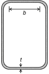
Axially loaded truss members, columns under combined axial load and bending, beam members in flexure, braces in seismic braced frames, and members of seismic moment resisting frames all have elements that experience compression under their design loads. The behavior of these elements can dictate the strength of the member and connection if their slenderness allows the onset of local buckling prior to full plastification of the section. As a result, limiting values for the slenderness of these elements are set to ensure that the capacity of the member and connection can be reached prior to local buckling or a lower design strength must be calculated. When the element in compression is part of a square or rectangular HSS member, it is considered stiffened due to the restraint provided by the supporting perpendicular walls and the width-thickness ratio, b/t, defines the slenderness of the element (Figure 1). AISC 360-10 (Chapter B4) defines the width, b, of an HSS member as the clear distance between the webs minus the inside corner radius on each side (b = B – 3t), where B is the outside width of the HSS member. The thickness, t, is taken as the design wall thickness (t = 0.93tnom for electric-resistance-welded A500 HSS or t = tnom for submerged-arc-welded or ERW A1085 HSS), where tnom is the nominal wall thickness. Meanwhile, Eurocode 3 (CEN 2005) defines the width-thickness ratio as the outside width of the HSS member minus two times the outside radius all divided by the wall thickness.
Focusing on compression elements in HSS subject to flexure under predominately static loads, AISC 360-10 (Table B4.1b, case 17) defines the maximum width-thickness ratio for an element to be considered compact as:

Equation 1 is adopted from Limit States Design of Steel Structures (CSA 2009) of the Canadian Standards Association and corresponds closely to the class 1 limit of Eurocode 3 (CEN 2005). HSS whose elements have width-thickness ratios below this limit will develop a fully plastic stress distribution prior to local buckling. The limit separating a compact and non-compact element, λr, is defined as:

which is the same limit that separates a non-slender and slender element in an HSS member under compression. However, lower limits are required for seismic design as research has shown that cyclic loading of square and rectangular sections can lead to premature fracture when local buckling occurs (Lui and Goel 1987; Sherman 1995).
For seismic design, not only is the ability to develop the full plastic stress distribution of the section desired, but also the ability to provide reliable and stable inelastic deformation to large deformation levels. AISC 341-05 (Table I-8-1) defined a more stringent seismically compact width-thickness limit for HSS members in flexure or flexural buckling:

This limit was not only applied to rectangular and square HSS braces in special concentrically braced frames, but also HSS braces in ordinary concentrically braced frames. The lower width-thickness limit is a direct result of research performed by Lui and Goel (1987) and Sherman (1995), which showed that a limit of λp(Equation 1) does not allow adequate inelastic behavior under cyclic loads. These studies found that when rectangular HSS braces undergoing reversed axial load form a local buckle, fracture occurs after only a limited number of cycles. A more recent study by Fell et al. (2006) on the behavior of concentric braces led to an approximately 15% reduction in the width-thickness ratio, λhd, specified in AISC 341-10 (Table D1.1) for highly ductile members that are expected to undergo stable inelastic behavior up to rotation levels of 0.04 rad. λhd is defined as:


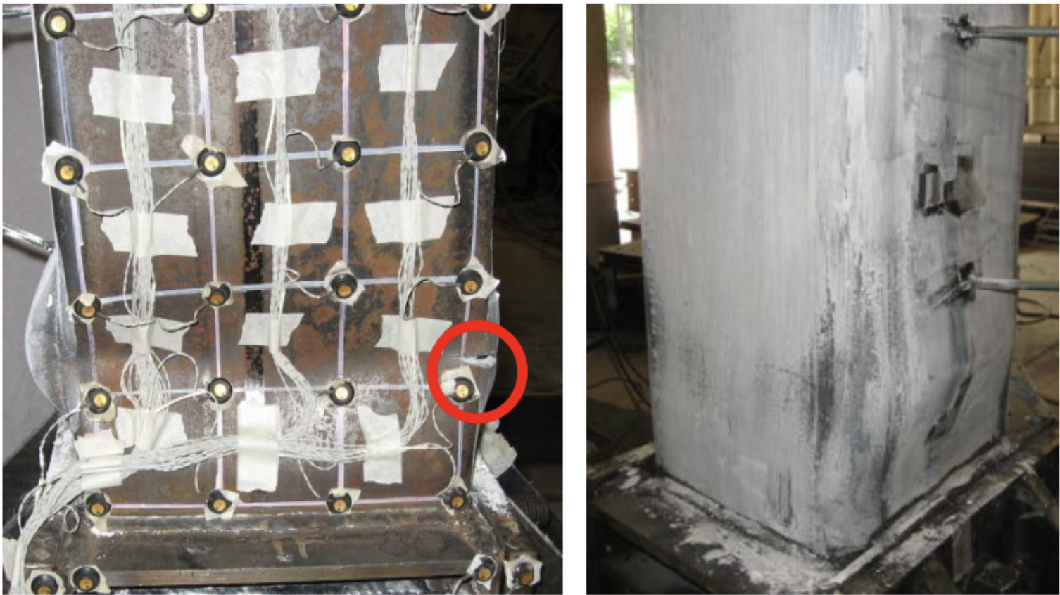
Research has shown that large strains in the plastic hinge region that form at the mid-point of a square and rectangular HSS brace member under seismic loads lead to the initiation of tearing at its corner. This process is amplified for rectangular HSS due to a concentration of localized strains during cycling leading to earlier fracture and smaller drift capacities (Sabelli et al. 2013). For moderately ductile members that are expected to maintain a stable performance up to rotation levels of 0.02 rad., the maximum width-thickness ratio, λmd, is the same as that given in Equation 3. However, it should be noted that since beam and column members are expected to undergo flexure (not flexural buckling), there is a relaxation of the moderately ductile width-thickness requirement to ??, which is typical of the moderately ductile limits for most member types. The recent more stringent width-thickness seismic requirements have severely limited the use of square and rectangular braces in seismic braced frame applications.
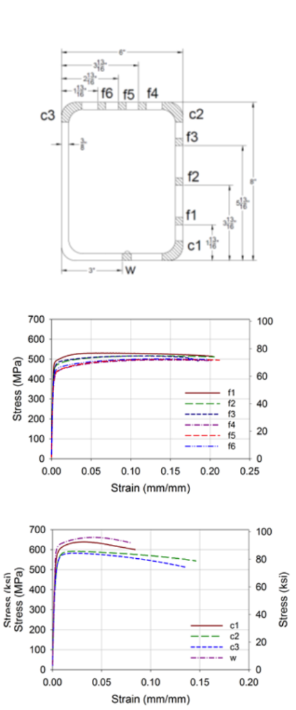
One reason for the lack of ductility and tearing that is seen to initiate at the corners of square and rectangular HSS members under cyclic loading has to do with the cold forming process. This process results in significant cold working at the corners of these sections and variability of the mechanical properties of the material around the cross-section of square and rectangular HSS members. Figure 2 shows the monotonic tensile properties of coupon specimens taken from different locations around an HSS 8x6x3/8 cross-section. In general, the average yield strength is approximately 20% higher for material taken from the corner as opposed to the flat, but the average ductility ratio for the corner coupons is 5.30 compared to 27.6 for the coupon specimens taken from the flats (Fadden and McCormick 2014). These properties along with cycling play a critical role in the initiation of tearing at the corners of square and rectangular braces leading to the restrictive width-thickness requirements for HSS members.


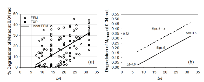
Figure 4b contains plots of Equation 5 and Equation 5 plus one standard deviation based on the 133 modeled sections. The results can be used to determine a potential limiting width-thickness ratio suitable for HSS beam members used in seismic moment resisting frames given the need to maintain 80% of the plastic moment of the beam member out to drift levels of 0.04 rad. Table 1 provides a comparison of the limiting width-thickness ratios based on Equation 5, Equation 5 plus one standard deviation, AISC 341-10 (λhd), AISC 341-05 (λps), AISC 360-10 (λp)and Eurocode 3 (class 1) assuming E = 29000 ksi and Fy = 46 ksi. Overall, the results suggest that local buckling may be a concern in the continued development of HSS-based seismic moment frame systems, but HSS members are available that will allow the seismic provisions to be met.


References
AISC. (2005). “Seismic Provisions for Structural Steel Buildings”. ANSI/AISC 341-05. American Institute of Steel Construction, Chicago, IL.
AISC. (2010). “Seismic Provisions for Structural Steel Buildings”. ANSI/AISC 341-10. American Institute of Steel Construction, Chicago, IL.
AISC. (2010). “Specifications for Structural Steel Buildings”. ANSI/AISC 360-10. American Institute of Steel Construction, Chicago, IL.
CEN (2005). “Eurocode 3: Design of Steel Structures – Part 1-1: General Rules and Rules for Buildings”. EN 1993-1-1:2005(E). European Committee for Standardization, Brussels, Belgium.
CSA (2009). “Limit States Design of Steel Structures”. CSA Standard S16-09. Canadian Standards Association, Rexdale, Ontario, Canada.
Fadden, F. and McCormick, J. (2012). “Cyclic Quasi-Static Testing of Hollow Structural Section Beam Members”. ASCE Journal of Structural Engineering, 138(5), 561-570.
Fadden, F. and McCormick, J. (2014). “Finite Element Model of the Cyclic Bending Behavior of Hollow Structural Sections”. Journal of Constructional Steel Research, 94, 64-75.
Fell, B.V., Kanvinde, A.M., Deierlein, G.G., Myers, A.T. and Fu, X. (2006). “Buckling and Fracture of Concentric Braces under Inelastic Cyclic Loading”. Steel Tips, Structural Steel Education Council, Moraga, CA.
Lui, Z. and Goel, S.C. (1987). “Investigation of Concrete-Filled Tubes under Cyclic Bending and Buckling”. UMCE Report 87-3. Department of Civil and Environmental Engineering, University of Michigan, Ann Arbor, MI.
Sabelli, R., Roeder, C.W., and Hajjar, J.F. (2013). “Seismic Design of Steel Special Concentrically Braced Frame Systems: A Guide for Practicing Engineers”. NEHRP Seismic Design Technical Brief No. 8, produced by NEHRP Consultants Joint Venture, a partnership of the Applied Technology Council and the Consortium of Universities for Research in Earthquake Engineering for the National Institute of Standards and Technology, Gaithersburg, MD, NIST GCR 13-917-24.
Sherman, D.R. (1995). “Stability Related Deterioration of Structures”. Proceedings of the Annual Technical Session and Meeting, Structural Stability Research Council, Bethlehem, PA.
July 2014