Weld Effective Lengths for Round HSS Connections
By Jeffrey A. Packer
Bahen/Tanenbaum Professor of Civil Engineering, University of Toronto, Ontario, Canada
The AISC Specification (AISC 2016) gives weld effective lengths for plate-to-rectangular HSS welded joints, and rectangular-to-rectangular HSS welded joints, in Section K5 of AISC 360-16. These are used to design welds between plate and HSS branches to rectangular HSS main members, whenever the welds are to be “fit for purpose” and not necessarily able to resist any force in the loaded branch. However, for round-to-round HSS connections the AISC Specification is noticeably silent, and there are no weld effective length rules given for such connections. As a consequence of this uncertainty there is a tendency for many designers to just specify complete joint penetration (CJP) groove welds for round-to-round HSS connections, which is an expensive and undesirable default practice.
It is known that the load distribution around a round HSS welded joint can be highly non-uniform (Marshall 1992). To deal with potential weld “unzipping”, caused by one part of a welded joint being much more highly loaded than another, AWS D1.1 (AWS 2015) – in its Clause 9.6.1.3(4) – implies that the weld effective length in axially loaded round-to-round HSS connections is equal to 1/1.5 of the total weld length under factored loads, regardless of the joint geometry. While believed to be conservative, this AWS rule is not supported by experimental evidence. A laboratory-based test program has hence been recently conducted to assess the performance of welds in round HSS connections. Weld-critical tests (where failure occurs by weld fracture) were completed on full-scale, round-to-round Cross- (or X-) connections (Tousignant and Packer 2017a, 2017b), and this article reports on the findings.
Experimentation

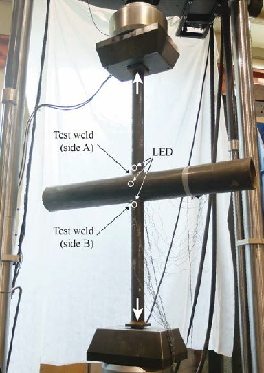
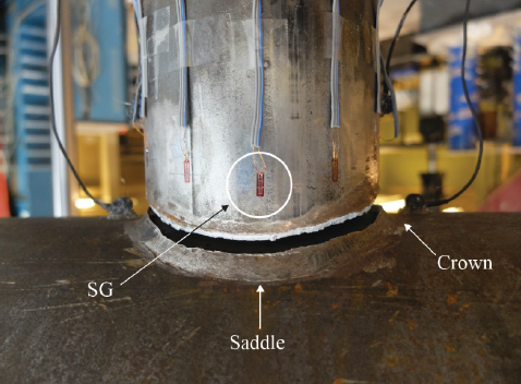
A total of 12 tests were performed on round-to-round Cross-connections, fabricated from large-size A500 (ASTM 2013) dual-certified Grade B and C HSS provided by Atlas Tube. Professional fabrication was provided by Walters Group, to achieve fillet welds all-around the branches using a semi-automatic flux-cored arc welding process with a CO2 shielding gas. The chord members were HSS 10.75 x 0.500 and HSS 16.00 x 0.500, with branches (at either 90° or 60°) selected to obtain branch-to-chord width ratios (β) ranging from 0.25 to 0.47. All test specimens had geometric configurations that permitted the use of fillet welding, per AWS D1.1. Welding procedure specifications were developed (in conjunction with trial sectioning) to achieve minimal but adequate root penetration, the welds were ground to ideal triangular shape, and careful measurements were made of the geometric and mechanical properties of the welds. Specimens were well-instrumented and loaded to failure by applying a quasi-static axial tension force to the end of the branches, as shown in Figure 1. Failure in all cases occurred in a brittle manner by fracture along a plane through the weld. A typical failure is shown in Figure 2, for a 90° connection.

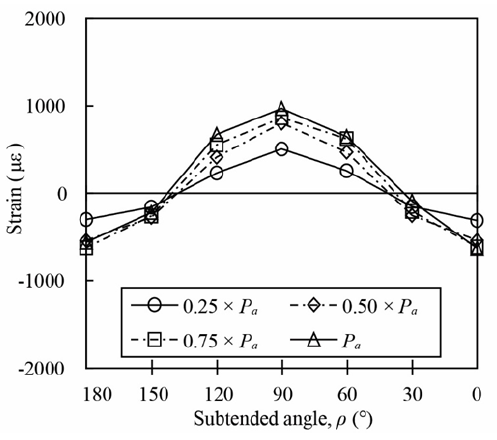
Strain gauges around the branch members close to the welds (such as indicated by SG in Figure 2) confirmed the non-uniform strain (and thus tensile load) distribution around the branch and hence in the neighboring weld. For the 90° connections, the tensile strain decreased as a function of distance away from the highly loaded saddle position (indicated in Figure 2). An example of this strain variation around the branch and weld is shown in Figure 3, for various load levels corresponding to 25%, 50%, 75% and 100% of the weld fracture load (Pa). In Figure 3, the “subtended angle” is the angle measured around the branch, with 0° and 180° corresponding to the crown points and 90° corresponding to the saddle point (see Figure 2). The tensile strain is therefore smallest at the crown, with much of the weld even remaining in compression for the entire tension load range. This non-uniform loading equates to an effective-length phenomenon, which is expectedly more pronounced for connections with higher β values where stiff membrane action dominates load transfer at the saddle points.

Evaluation
The foregoing experimentally observed weld-effective-length trends will be prevalent in all round-to-round HSS connections of similar geometries, regardless of the weld type (fillet, PJP, CJP) used to join branches to chord (assuming that the welds do not significantly change the footprint of the branches). More data is now being developed, by means of numerical finite element studies, to map the effective length trends in more detail. The question that remains is how to apply this knowledge of weld effective lengths to the actual design of welds in round-to-round HSS connections. As with the current application of weld effective length rules to rectangular HSS connections (AISC 360-16 Chapter K), this is intimately tied to the simplified rules for the design of weld types that are currently in use (AISC 360-16 Chapter J), along with their assigned resistance or safety factors.
For CJP groove welds any use of effective length factors for welds is a moot point. By definition the strength of a CJP weld exceeds the capacity of the attached branch wall at every point along its length, so CJP welds become non-critical at all points along their length, regardless of load distribution, and hence weld effective lengths are unnecessary. The experimental study described above was performed entirely with fillet welds around the branches, so it is interesting to examine the weld ultimate strengths to investigate the suitability of the AWS D1.1 weld effective length (2/3 of the total weld length) for fillet-welded joints. The total weld length (at the root of the fillet weld) for the 12 test welds was determined from 3D solid models of intersecting cylinders, but it can also be determined from the slightly conservative approximation for total weld length given in AWS D1.1 Clause 9.5.4:

To assess whether adequate or excessive safety margins are inherent in any weld design approach, the structural reliability (or safety index) can be calculated for a set of test data and compared to the minimum target value. The value for the latter, for structural connectors such as welds, is currently 4.0 (AISC 360-16 Section B3.1 of the Specification Commentary). Using the nominal strength of fillet welds prescribed by AISC 360-16 in Clause J2.4a, along with a resistance factor for fillet welds of 0.75, a simplified reliability analysis yields a safety index of 5.6 for the test results herein, if:
(i) Weld effective lengths are ignored and the total weld length is used;
(ii) The AISC/AWS fillet weld directional strength-enhancement factor of (1 + 0.50sin1.5θ), as described in AISC 360-16 Section J2.4b and AWS Clause 2.6.4.2, is not used. Note that the application of this fillet weld directional strength-enhancement factor is not recommended for the design of fillet welds in HSS connections because it has been previously found to be generally unsafe (Packer et al. 2016, Tousignant and Packer 2017c). It would, moreover, be very hard for designers to apply this to round-to-round HSS connections because the direction of loading on the weld changes along the weld length, since the local or dihedral angle continually varies and is not equal to the branch inclination angle.
It can be concluded, then, that the current AISC Specification fillet weld design provisions provide adequate structural reliability (safety index ≥ 4.0) without weld effective lengths (i.e. when the total weld length is used to determine the weld strength), assuming the fillet weld directional strength-enhancement factor is not used. It should be noted that this deduction is based on a limited experimental study of round-to-round Cross-connections with a modest geometric parameter range. Extension to a wider range of connection types and to PJP groove welds is a future objective.
References
AISC. 2016. “Specification for structural steel buildings”, ANSI/AISC 360-16, American Institute of Steel Construction, Chicago, IL.
ASTM. 2013. “Standard Specification for Cold-Formed Welded and Seamless Carbon Steel Structural Tubing in Rounds and Shapes”, ASTM A500/A500M-13, American Society for Testing and Materials, West Conshohocken, PA.
AWS. 2015. “Structural welding code – Steel”, AWS D1.1/D1.1M:2015, American Welding Society, Miami, FL.
Marshall, P.W. 1992. “Design of welded tubular connections – Basis and use of AWS code provisions”, Elsevier, Amsterdam, The Netherlands.
Packer, J.A., Sun, M. and Tousignant, K. 2016. “Experimental evaluation of design procedures for fillet welds to hollow structural sections”, Journal of Structural Engineering, American Society of Civil Engineers, Vol. 142, No. 5, pp. 04016007-1 – 04016007-12.
Tousignant, K. and Packer, J.A. 2017a. “Investigation of weld effective length rules for CHS X-connections”, Proceedings of the 16th International Symposium on Tubular Structures, Melbourne, Australia.
Tousignant, K. and Packer, J.A. 2017b. “Fillet Weld Effective Lengths in CHS X-Connections. I: Experimentation”, Journal of Constructional Steel Research, Vol. 138, pp. 420-431.
Tousignant, K. and Packer, J.A. 2017c. “Numerical investigation of fillet welds in HSS-to-rigid end-plate connections”, Journal of Structural Engineering, American Society of Civil Engineers, Vol. 143, No. 12, pp. 04017165-1 – 04017165-16.
October 2017