Stepped HSS T- and Cross-Connections Under Branch In-Plane and Out-of-Plane Bending
By Jeffrey A. Packer
Bahen/Tanenbaum Professor of Civil Engineering, University of Toronto, Ontario, Canada
Moment-resisting connections are sometimes required between square and rectangular HSS members that are welded directly to each other in a T- or Cross-connection configuration. If the branch-to-chord width ratio (β) is less than unity (i.e., the connection is “stepped”), the connection will generally not be fully rigid and will only be a partially restrained (PR) moment connection. As such, the connection will transfer moment, but the rotation between the connected members will not be negligible, and in the analysis of the structure the force-deformation response characteristics of the connection need to be included (AISC Specification 360-16 B3.4b(b)). Determination of the moment capacity of stepped HSS connections under branch bending is covered by AISC 360-16 K4.3, which refers to a small amount of information in Table K4.2 and to the broad coverage in Chapter J. This article thus provides more specific guidance, by examination of the potential failure modes or limit states.
Limit States
For both branch in-plane and out-of-plane bending, the limit states for stepped moment connections can be inferred from similar failure modes for T- and Cross-connections under branch axial loading. The common limit states (within the scope of AISC 360-16 Sections J10 and K1.2a) will be: (i) plastification of the chord connecting face; (ii) shear yielding (or “punching shear”) of the chord connecting face; (iii) local yielding of the branch in a T-connection (or branches in a Cross-connection) due to uneven load distribution in the branch(es). The connection moment capacity for each of these failure modes can be determined by using the Principle of Virtual Work, applied to assumed failure mechanisms or models. Solutions are derived below, for the separate cases of branch in-plane (ip) bending and branch out-of-plane (op) bending.
Branch In-Plane Bending
Limit State of Chord Plastification
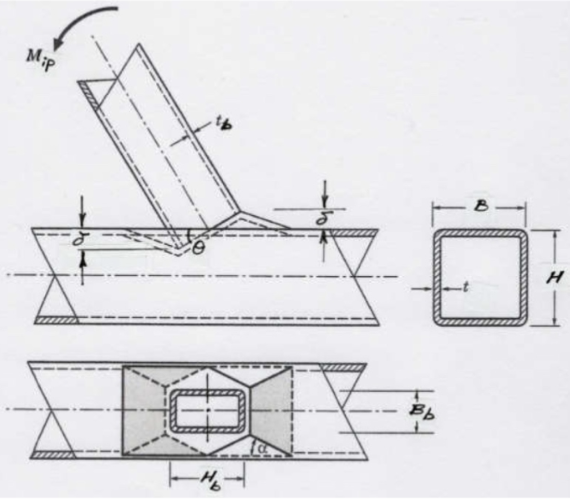
This can be analysed using a rectilinear yield-line mechanism in the chord connecting face, as shown in Figure 1. (This mechanism is also shown in a generic form in Fig. 9-5(b) of the AISC Manual (AISC, 2017)). In this case the external work done by the applied load is the moment, Mip, multiplied by the virtual rotation, θ=δ/(Hb/2), where δ a small virtual displacement. The internal work done, assuming rigid-plastic behavior, can be taken as the work expended in plastic rotation of all the yield lines, which is given by 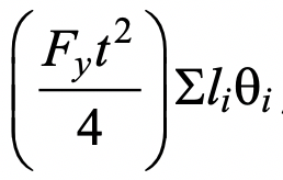 , where li is the length of yield line i, θi is the corresponding rotation of yield line i, and
 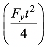 is the plastic moment of resistance per unit length of the chord face. Equating the internal and external work done, the small virtual displacement/rotation terms cancel out and an expression for the nominal in-plane moment capacity, Mn-ip, can be obtained. This then needs to be minimized with regard to the unknown length of the yield-line pattern shown in Figure 1, by differentiating the Mn-ip expression with respect to the angle α. This yields the following minimum nominal moment capacity:

where η is a non-dimensional bearing length ratio equal to 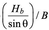 and θ in Eq. (1) takes into account a possible branch-to-chord member angle of inclination. Qf is an added factor, derived empirically from connection tests, that takes account of the influence of chord connecting face compressive stress on the connection capacity, and is given by AISC 360-16 Eq. (K3-14). A resistance factor of φ = 1.0 (or Ω = 1.50) would apply to Eq. (1), consistent with other yield line equations in AISC 360-16, to produce a connection available flexural strength.
Limit State of Chord Shear Yielding (Punching Shear)
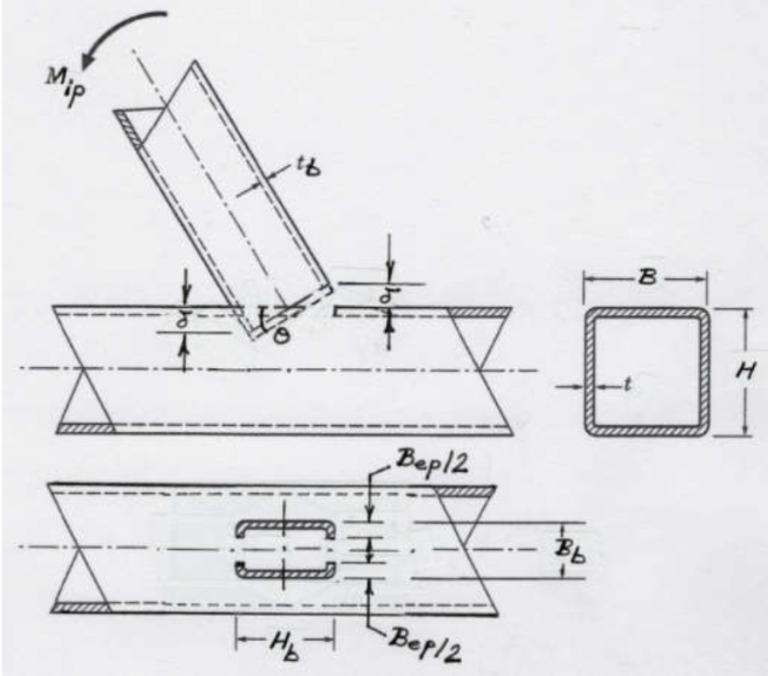
Due to non-uniform loading around the cross-section of the branch member adjacent to the chord connecting face, only part of each transverse branch wall will be effective, shown by the shaded parts of the branch in Figure 2. Regardless of loading (axial, in-plane bending, or out-of-plane bending), the longitudinal branch walls will be fully effective (because they are adjacent and parallel to the stiff chord sidewalls), while the transverse branch walls will have varying degrees of effectiveness (because they are supported by the flexible chord face). The welds and chord face immediately adjacent to the highly loaded parts of the branch will also be highly loaded. Thus, if chord punching shear is to occur it will take place along the two U-shaped segments, each of length Hb + Bep (see Figure 2). The amount of branch rotation to punch through the chord thickness is such that δ = t . Through-thickness punching will initiate in the four Bep / 2 zones, tapering to zero punching at the axis of rotation.
The external work done is Mipθ = Mipt / (Hb / 2) which can be equated to the internal work done by shear forces multiplied by average displacements. Taking the shear yield stress as 0.6Fy one obtains:

for the nominal moment capacity, and θ in Eq. (2) takes into account a possible branch-to-chord member angle of inclination. The punching shear effective width term, Bep, is given by:
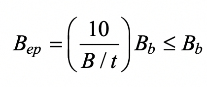
A resistance factor of φ = 1.0 (or Ω = 1.50) would apply to Eq. (2), consistent with AISC 360-16 Eq. (J4-3), to produce a connection available flexural strength, and similarly a chord stress influence function, Qf, is not applied.
Limit State of Local Yielding of Branch(es) due to Uneven Load Distribution
As explained previously, the effective portions of the branch correspond to the shaded portions in Figure 2, except Bep (the chord effective width for punching shear) in Figure 2 must be replaced by the term Be (the branch member effective width). These are different because the branch member effective width is influenced by the relative strengths of the branch and the chord on which it rests, whereas the chord punching shear effective width (Eq. (3)) is independent of the branch properties. AISC 360-16 Eq. (K1-1) gives the effective width of one branch transverse wall as:

Assuming a compact branch member, the branch nominal moment capacity may be derived by subtracting the moment contribution of the non-effective “flange” portions from the branch (in-plane) plastic moment capacity. Thus, for an inclined branch,

where Zb is the plastic section modulus of the branch about the axis of bending. Re-arranging terms and simplifying the moment arm to (Hb/sinθb) one obtains:

A resistance factor of φ = 0.95 (or Ω = 1.58) can be applied to Eq. (5), consistent with the same limit state for an axially loaded branch in AISC 360-16 Table K3.2, to produce a connection available flexural strength. The chord stress influence function,Qf, is not included because this is a branch failure mode.
Branch Out-of-Plane Bending
Limit State of Chord Plastification
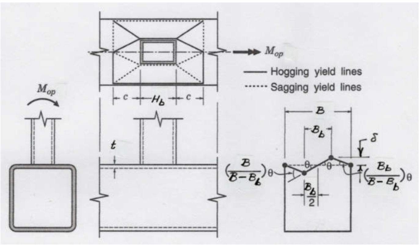
This can be analysed using a rectilinear yield-line mechanism in the chord connecting face, as shown in Figure 3. (This mechanism is also shown in a generic form in Fig. 9-5(c) of the AISC Manual (AISC, 2017)). In this case the external work done by the applied load is the moment,Mop, multiplied by the virtual rotation, θ = δ / (Bb / 2), where δ is a small virtual displacement. The internal work done can be calculated in an analogous manner to the case of in-plane bending, and hence the nominal out-of-plane moment capacity, Mn-op, can be obtained. After optimization of length c in Figure 3, the following minimum nominal moment capacity can be determined:

The chord stress influence factor, Qf, given by AISC 360-16 Eq. (K3-14) is again included. A resistance factor of φ = 1.0 (or Ω = 1.50) would apply to Eq. (6), consistent with other yield line equations in AISC 360-16 and the in-plane bending case, to produce a connection available flexural strength.
Limit State of Chord Shear Yielding (Punching Shear)
As explained previously, if chord punching shear is to occur it will take place along the two U-shaped segments, each of length Hb + Bep (see Figure 2), even under branch out-of-plane bending. Again, the branch can be imagined to just punch through the chord thickness at the furthest point from the axis of rotation. Thus, through-thickness punching will initiate along the two Hb lines, tapering to zero punching at the axis of rotation. The external work done is Mopθ = Mopt / (Bb / 2) which can be equated to the internal work done by shear forces multiplied by average displacements. Taking the shear yield stress as 0.6Fy one obtains:

for the nominal moment capacity. The punching shear effective width term,, is given by Eq. (3). A resistance factor of φ = 1.0 (or Ω = 1.50) would apply to Eq. (7), consistent with AISC 360-16 Eq. (J4-3), to produce a connection available flexural strength, and the chord stress function, Qf, is not applied.
Limit State of Local Yielding of Branch(es) due to Uneven Load Distribution
The effective portions of the branch again correspond to the shaded portions in Figure 2, even under branch out-of-plane bending, but Bep(the chord effective width for punching shear) in Figure 2 must be replaced by the term Be(the branch member effective width) given by Eq. (4).
Assuming a compact branch member, the branch nominal moment capacity may be derived by subtracting the moment contribution of the non-effective portions of the branch transverse walls from the branch (out-of-plane) plastic moment capacity. Thus,

where Zb is the plastic section modulus of the branch about the axis of bending. Re-arranging, gives:

A resistance factor of φ = 0.95 (or Ω = 1.58) can be applied to Eq. (8), with no Qf factor, as for this limit state under in-plane bending, to produce a connection available flexural strength.
Limit State of Chord Distortional Failure
This additional limit state is cited as a potential failure mode for stepped rectangular HSS connections whenever a torque is applied to the chord member. This failure mode involves rhomboidal distortion of the chord cross section, with the torsional capacity given by (AISC 360-16 Eq. (K4-7)):

AISC 360-16 Table K4.2 gives a resistance factor of φ = 1.00 (or Ω = 1.50) for Eq. (9), as it is associated with a yielding failure mode.
References
AISC. 2016. “Specification for Structural Steel Buildings”, ANSI/AISC 360-16, and Commentary, American Institute of Steel Construction, Chicago, IL.
AISC. 2017. “Steel Construction Manual”, 15th edition, American Institute of Steel Construction, Chicago, IL.
March 2019