Rectangular HSS K-Connections with Zero Gap
By Jeffrey A. Packer
Bahen/Tanenbaum Professor of Civil Engineering, University of Toronto, Ontario, Canada
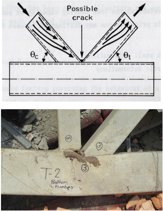
If one refers to design guidance for rectangular HSS K-connections in AISC 360-16 Chapter K, it can be seen that such connections need to be designed and fabricated either with a minimum gap between the branch members’ toes at the chord face, or with a minimum overlap of the branch members at the chord face (Limits of Applicability in Table K3.2A). Hence, welding the branch members toe-to-toe (i.e. with zero gap) is not covered by the Chapter K design provisions. However, as noted in AISC 360-16 Section K1 … “Connections not complying with the limits of applicability listed are not prohibited and must be designed by rational analysis”.
AISC and other international design recommendations for HSS have avoided advocating for zero-gap K- (or N-) connections because the branch toes represent a highly stressed region, as indicated by the load path in Figure 1(a), and, if inadequate welding is performed at the branch toes, such as just welding one branch to the other branch, structural failure is possible, as exemplified by Figure 1(b).
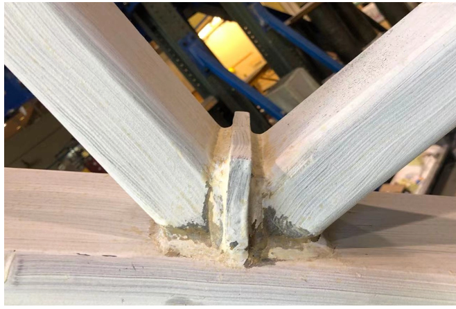
For K-connections with zero gap, or a very small gap, or a very small overlap, designers have often resorted to welding a division plate to the chord between the branches, and then fillet-welding both branches to this plate and the chord (Figure 2). This easy-to-weld alternative produces a stiffened and acceptable connection, with a strength exceeding that of the gapped K-connection, but it may not satisfy aesthetic standards for some projects.
Research on “Zero-Gap” K-Connections
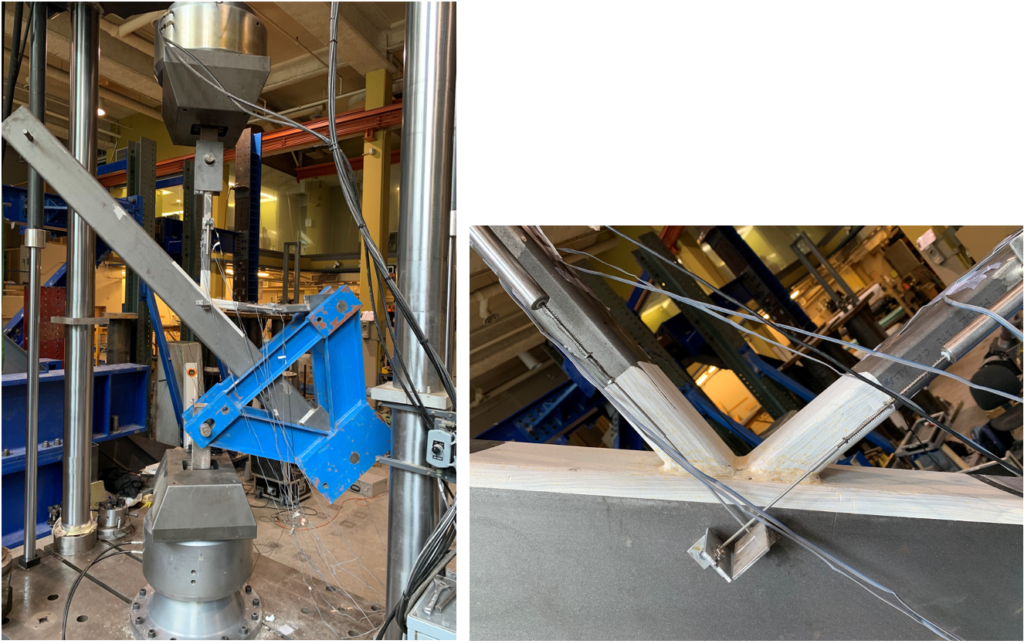
Since the zero-gap welded K-connection is seen in practice, the Steel Tube Institute sponsored research into this connection to determine its feasibility. Testing was performed in the laboratory (Figure 3), using a purpose-built self-reacting K-connection test jig (shown in blue) within a universal testing machine. To accompany the experimentation, an analytical model for failure of such connections was derived, finite element (FE) models were built and validated, then the FE models were used to generate many more “numerical tests” over a wide range of connection parameters, to form a large database of results (Bu and Packer, 2022).
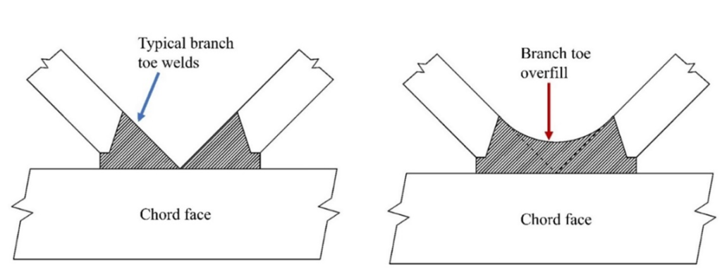
From this research, it was concluded that rectangular HSS zero-gap (and small gap) K-connections were indeed feasible, provided the branch toes are properly beveled and welded to the chord face with prequalified CJP groove welds in accordance with AWS D1.1 (AWS, 2020), as shown in Figure 4(a). Overfilling with weld in the branch-to-branch region will increase the connection capacity, provided the branch toes are initially welded in a proper manner to the chord face (Bu and Packer, 2022), as indicated in Figure 4(b).
To calculate the design resistance of zero-gap or small gap welded K-connections, the available strength expression for the chord face plastification failure mode for conventional “large-gap” K-connections, such as found in prEN 1993-1-8 Part 9 (CEN, 2021) or AISC 360-16 Table K3.2 Eq. (K3-7) (AISC, 2016), can be used with a small reduction (5%) over the following range (which represents the scope of the numerical parametric study): gap dimension (g) from zero up to the sum of the branch wall thicknesses (tb1 + tb2) , branch-to-chord angles (ϴ) between 30o and 60o, chord wall width-to-thickness ratio (B/t) between 10 and 40, and branch-to-chord width ratios (β = Bb/B) between 0.38 and 0.75 (Bu and Packer, 2022).
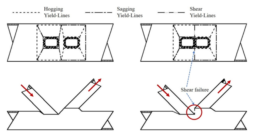
Alternatively, the connection nominal strength, Pn, of a zero-gap or small gap welded K-connection can be predicted closely by the analytical solution given as Eq. (1), which is based on a chord face yield line solution modified by replacing flexural yield lines in the gap region (Figure 5(a)) with a single shear yield line (Figure 5(b)). Eq. (1) is thus a substitute for Eq. (K3-7) in AISC 360-16 Table K3.2 (AISC, 2016).

In Eq. (1), B and Bb are the dimensions of the chord and branch, respectively, perpendicular to the plane of the connection, and Hb is the branch dimension in the plane of the connection. The chord yield stress, Fy, presumes regular-strength HSS up to 50 ksi, t represents the design wall thickness of the chord, and Qf is a function to cater for compression stress in the chord connecting face, given by Eq. (K3-15) in AISC 360-16 (or is taken as unity for tension stress in the chord connecting face). To determine the connection available strength – expressed as an axial force in either branch – from Eq. (1), a resistance factor of ϕ = 0.9 is recommended. Eq. (1) is also valid over the same ranges of g, ϴ, B/t, and β as described above. In addition to this limit state of combined plastification and shear failure of the chord connecting face, other potential K-connection limit states should still be checked, namely shear of the chord sidewalls and local yielding of the branch members due to uneven load distribution, when connection geometric parameters deem them applicable.
References
AISC. 2016. “Specification for Structural Steel Buildings”, ANSI/AISC 360-16, American Institute of Steel Construction, Chicago, IL.
AWS. 2020. “Structural Welding Code – Steel”, ANSI/AWS D1.1/D1.1M:2020, 24th. edition, American Welding Society, Miami, FL.
Bu, X.-D. and Packer, J.A. 2022. “RHS-to-RHS Zero-Gap K-Connections”, Journal of Structural Engineering, American Society of Civil Engineers, Vol. 148, No. 6, 04022055-1 – 04022055-18.
CEN. 2021. “Eurocode 3: Design of Steel Structures – Part 1-8: Design of Joints”, prEN 1993-1-8, European Committee for Standardization, Brussels, Belgium.
July 2022