Modeling HSS Trusses
By Jeffrey A. Packer
Bahen/Tanenbaum Professor of Civil Engineering, University of Toronto, Ontario, Canada

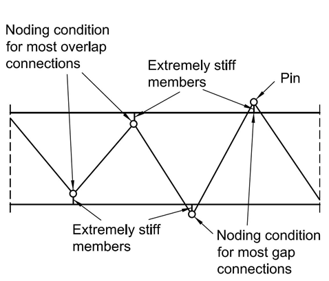
In AISC 360-16 Specification Tables K3.1 and K3.2, HSS K-connection available strength limit state formulas pertain only to the case of branches subject to axial loading. The Commentary to Section K3 explains that this is a result of the recommended truss analysis methods; namely (a) pin-jointed analysis, or (b) analysis using web members pin-connected to continuous chord members, as shown in Figure 1. Pin-jointed analysis has historically been a natural tool for truss analysis because it can be used in hand calculations, but nowadays frame analysis computer programs are the norm for truss analysis. This opens up options, such as that in Figure 1, but the question often arises as to whether such a model best represents real HSS truss behavior.

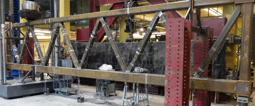
A number of large-scale, welded, HSS trusses with gapped or overlapped connections has now been tested in laboratories world-wide, such as shown in Figure 2, so test evidence has been assembled to evaluate various truss analysis methods (Frater and Packer, 1992; Tousignant and Packer, 2018).
To satisfy fabrication preferences, or even to satisfy connection parameter limits of applicability (such as in the AISC 360-16 Specification Tables K3.1A and K3.2A), the web centerlines must often intersect away from the centerline of the chord. This results in a so-called noding eccentricity, e, or offset of the work point (Figure 3), which can create significant primary bending moments in the chord members. A positive eccentricity (+e) is typically associated with gapped K-connections, while a negative eccentricity (-e) is typically associated with overlapped K-connections.

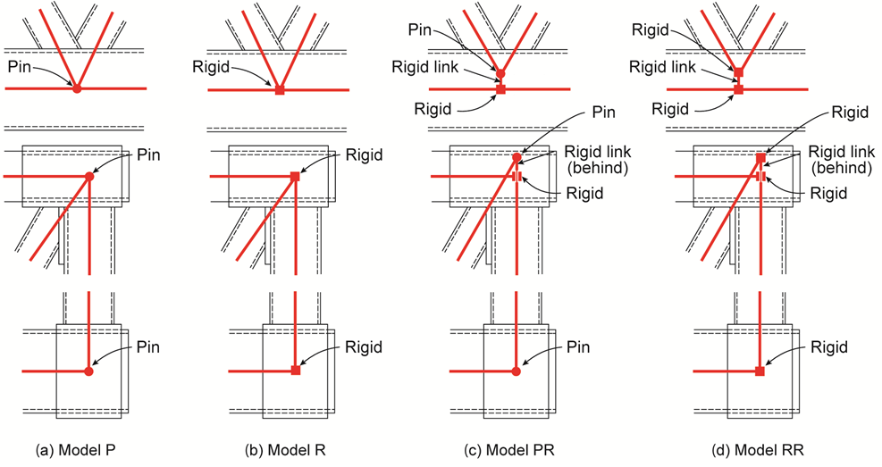
Frame-analysis models for predicting static elastic response (axial forces, bending moments, and deflections) in planar, welded, HSS trusses, which can be easily implemented in commercial frame-analysis computer programs, have centered on the following four practical methods (see Figure 4):

1. Model P (pinned): member segments are pin-ended, and connected concentrically at all joints regardless of e (Figure 4(a));
2. Model R (rigid): member segments are fixed at their ends, and connected concentrically at all joints regardless of e (Figure 4(b));
3. Model PR (pinned-rigid): chord members are continuous and web members are pin-ended, with the distance e modeled as a rigid two-joint link (Figure 4(c) and Figure 1);
4. Model RR (rigid-rigid): chord members are continuous and web members are fixed at their ends, with e modelled as a rigid two-joint link.
Models P and R may be considered as “concentric models”, since joints are modeled concentrically regardless of the actual value of e. It is therefore necessary to modify the truss geometry in the frame analysis program, when joints are eccentric, so that webs intersect the chord at a common point. This can be done by changing either the centerline-to-centerline chord depth, or the web-to-chord included angles (θ). It is recommended that the chord depth be maintained, which means adjusting θ. One should note that when e = 0 at all joints, Models R and RR are identical.
Evaluation of Models against Test Results
A set of 35 tests on point-loaded, simply supported trusses with both gapped and overlapped welded connections, branch-to-chord width ratios ranging from 0.40 to 0.86, and truss span-to-depth ratios ranging from 4 to 15, has been studied (Tousignant and Packer, 2018), resulting in the following conclusions:
For the ultimate limit state (ULS) design of HSS truss members and their connections, an accurate prediction of member axial forces is paramount. All four analysis methods gave very good estimates of the member axial forces, with model P generally being the most conservative. Significant bending moments are shown to occur in the truss members but, since the web moments tend to reduce to near-zero at the ultimate limit state due to connection plasticity and load re-distribution (Parcel and Murer, 1934; Wardenier, 1982), the prediction of chord member moments is of more significance. In that regard, models PR and RR give reasonable predictions and both take the primary moments in the chords produced by connection noding eccentricity into consideration (unlike models P and R). This is useful for designing the chord members for combined forces (flexure and axial force) using AISC 360-16 Specification Section H1. If analysis is performed using model RR the web member moments generated can be ignored, for both web member design (using AISC 360-16 Specification Chapters D & E) and connection design (using AISC 360-16 Specification Chapter K).
For the serviceability limit state (SLS) design of HSS trusses, to AISC 360-16 Specification Chapter L and ASCE/SEI 7 (ASCE, 2016), a reliable method for predicting the maximum truss deflection is required. At specified-load levels all four analysis methods give good estimates of the maximum truss deflection, but they generally err slightly on the un-conservative side – especially for trusses with the more-flexible gapped connections. Thus, if analysis is performed using model PR or model RR, a magnification factor of 1.1 on computed truss deflections is recommended for trusses with overlapped connections, and a magnification factor of 1.2 on computed truss deflections is recommended for trusses with gapped connections.
References
AISC. 2016. “Specification for structural steel buildings”, ANSI/AISC 360-16, and Commentary, American Institute of Steel Construction, Chicago, IL.
ASCE. 2016. “Minimum design loads and associated criteria for buildings and other structures”, ASCE/SEI 7-16, American Society of Civil Engineers, Reston, VA.
Frater, G.S. and Packer, J.A. 1992. “Modelling of hollow structural section trusses”, Canadian Journal of Civil Engineering, Vol. 19, No. 6, pp. 947 – 959.
Parcel, J.I. and Murer, E.B. 1934. “The effect of secondary stresses upon ultimate strength”, Proceedings (with discussions in Transactions) of the American Society of Civil Engineers, Vol. 60, Reston, VA, pp. 55.
Tousignant, K. and Packer, J.A. 2018. “Analysis of rectangular hollow section trusses”, Canadian Journal of Civil Engineering, In press.
Wardenier, J. 1982. “Hollow section joints”, Delft University Press, Delft, The Netherlands.
March 2020