Mechanical Properties of HSS Corners Versus Flats
By Jeffrey A. Packer
Bahen/Tanenbaum Professor of Civil Engineering, University of Toronto, Ontario, Canada
Min Sun
Assistant Professor, University of Victoria, British Columbia
It is well known that cold-formed square and rectangular HSS have a very high degree of cold working, and this raises the overall cross-section yield strength considerably. Relative to the flats, the cold forming causes an increase in the corner yield stress, an increase in the ultimate tensile strength and a decrease in the ductility (measured by the elongation at rupture). These mechanical properties vary with HSS width/depth and thickness, corner radius, grade and type of hot-rolled coil material, and by production method. This article hence summarizes mechanical property data from cold-formed HSS measured at the University of Toronto laboratories, over many projects. Typical engineering stress-strain curves for tensile coupons, taken longitudinally from four corners and three flats of a single cold-formed HSS member, are shown in Figure 1 (Ritchie et al., 2017a). Note that strain is actually dimensionless and 6.89 MPa = 1 ksi.
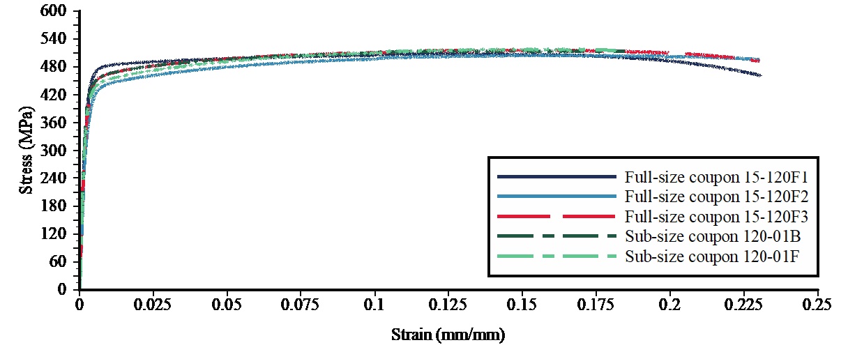
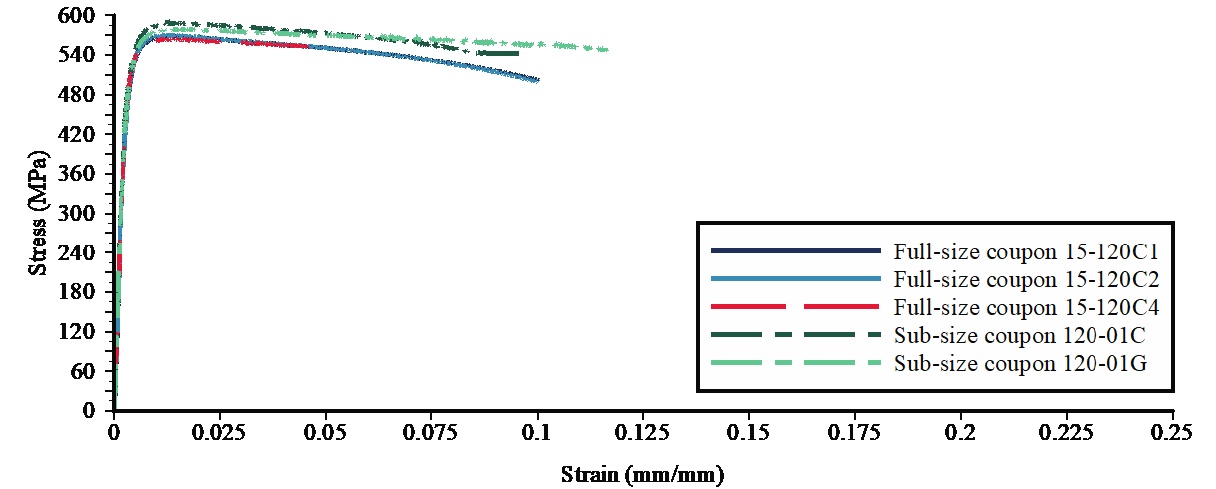
Figure 1: Static stress-strain curves from tensile coupon tests on HSS 120x120x6 (HSS 4¾ x 4¾ x ¼)
Representative mechanical properties, from both the flats and corners, are of particular interest for refining designs for dynamically loaded HSS, including blast, impact and seismic applications (Ritchie et al., 2017b). With regard to seismic loading, the capacity of the corners to withstand repeated inelastic load cycles is important when HSS are used as energy-dissipative braces. Also, the elevated yield stress in the corners is currently being investigated as a rationale for an increased Fy value for seismic design of such braces. (Recall that the nominal or minimum Fy guaranteed by the HSS producer is based on tensile coupons taken from the flats). Corner property data is also important to advance the science of hot-dip galvanizing cold-formed HSS.
Testing Method
Standard longitudinal tensile coupons, cut from the three flat sides excluding the weld seam and from the corners of square/rectangular HSS, have been machined to a specified dog-bone shape and tested under displacement control in a quasi-static manner in accordance with ASTM standards E8 (2016) and A370 (2017). The yield stress was determined using the 0.2% strain offset method, strain was measured over a prescribed gage length using a clip-gage extensometer, and elongation at failure (rupture strain) was determined after tests were completed by joining the fractured pieces together and recording the change in gage length divided by the initial gage length, as shown in Figure 2.
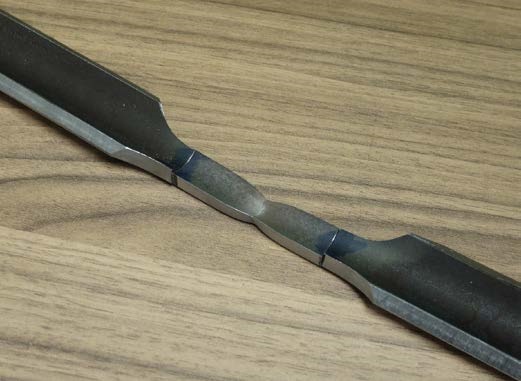
For the corner coupons, the correct curved shape (as in the parent HSS) was maintained during tensile testing by placing a curved block to fit snugly inside the corner radius, so that the coupon ends would not flatten when gripped by the universal testing machine. This is important, in order that the tensile behavior of the tested corner samples reflects the in-situ corner behavior.
The cross-sectional dimensions in the gage length of flat tensile coupons were carefully measured using a micrometer. For the curved corner coupons, the cross-sectional area in the reduced-width gage length can be determined by either: (i) weighing a sample, carefully cut at the gage marks and dividing the mass obtained by the initial gage length and the nominal density of rolled steel = 7850 kg/m3 (CISC 2016) or 490 lb/ft3 (AISC 2017) ; or (ii) placing the cross-section of a cut-and-machined sample from the elastic gage region (as done in Figure 2) on a flat-bed scanner and then determining the area using CAD software. The cross-sectional areas can also be checked with the equation given in Section 7.2.3 of ASTM E8 (2016), using the measured outside corner radii and the widths and thicknesses of the specimens (which is considered a less accurate method).
Test Data
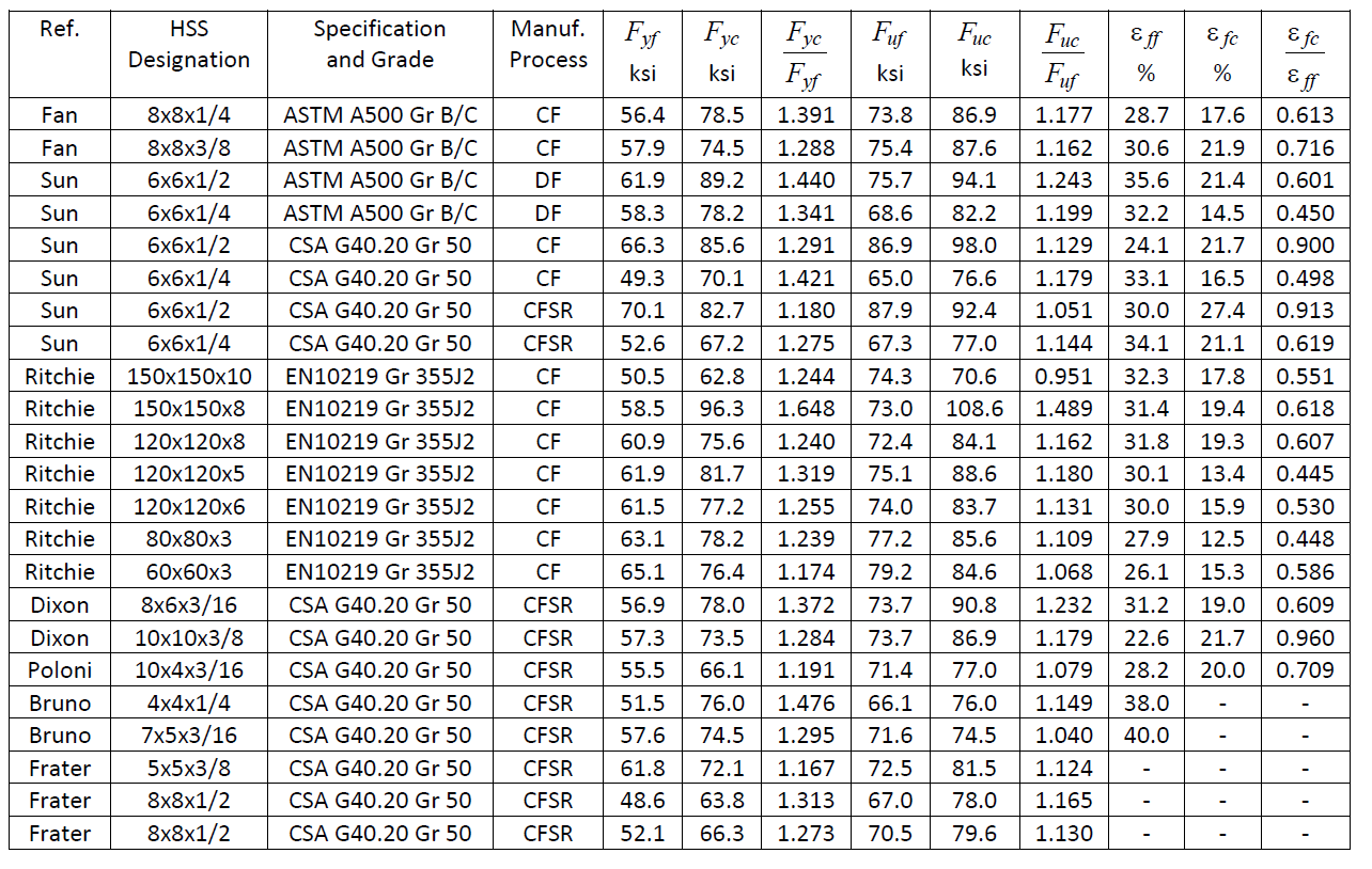
The results of mechanical property tests on 23 cold-formed HSS members are given in Table 1, where each entry is generally the average from several coupons from the flat portions, or several coupons from the corner regions, of that member. The material tested has been obtained from multiple producers across North America and Europe. The data has been compiled from theses by: Dixon (1983), Bruno (1984), Poloni (1985), Frater (1986, 1991), Sun (2014), Fan (2017) and Ritchie (2017).
Table 1: Static tensile test results for longitudinal coupons taken from the flats and corners of cold-formed square/rectangular HSS
Notes:
HSS Designation: in. x in. x in., or mm x mm x mm for European sections
Manufacturing Process: CF = continuous-formed; DF = direct-formed; CFSR = continuous-formed + stress-relieved
by heat treatment at 850°F (450°C) or higher, followed by cooling in air
Fyf and Fyc = yield stresses measured in the flat and corner positions, respectively, by the 0.2% strain offset method
Fuf and Fuc = ultimate stresses measured in the flat and corner positions, respectively
ε ff and ε fc = elongation at failure (fracture) measured in the flat and corner positions, respectively
All HSS tabulated are cold-formed, generally by the popular continuous forming method into a circular shape and then shaping to a square/rectangular size (CF). In some cases these sections were subsequently stress-relieved by heat treatment to 850°F or higher, followed by cooling in air (CFSR), which is an option available with ASTM A1085 Supplementary Requirement S1 (ASTM 2013a) and CSA G40.20/G40.21 Class H (CSA 2013). Two of the sections in Table 1 were direct-formed to square/rectangular shape (DF) from flat coil material. As the DF process produces a different strength and ductility distribution around the cross section compared to the CF process, the two DF sections have been omitted from the subsequent statistical analysis given below.
The HSS full-section average tensile strength, Fyave , can be computed by considering the yield stresses of the flat and corner regions from Table 1, weighted according to their respective contributions to the cross-sectional area, by:
Fyave=CFyc+(1-C)Fyf
Equation (1)
where C is the ratio of the corner areas to the full cross-sectional area of the HSS member, Fyc is the yield stress of the corner regions, and Fyf is the yield stress of the flats.
In Figures 3, 4 and 5, test data from Table 1 are shown in green for CF, red for CFSR, and blue for DF. Figure 3 shows the distribution of the corner-to-flat yield stress ratios, for which the mean for the 21 CF/CFSR sections is 1.30 and the coefficient of variation (COV) is 8.7%. Interestingly, the Fyc /Fyf ratios are generally similar for both CF and CFSR HSS, indicating that heat treatment tends to stress relieve the corners and flats in a proportional manner.
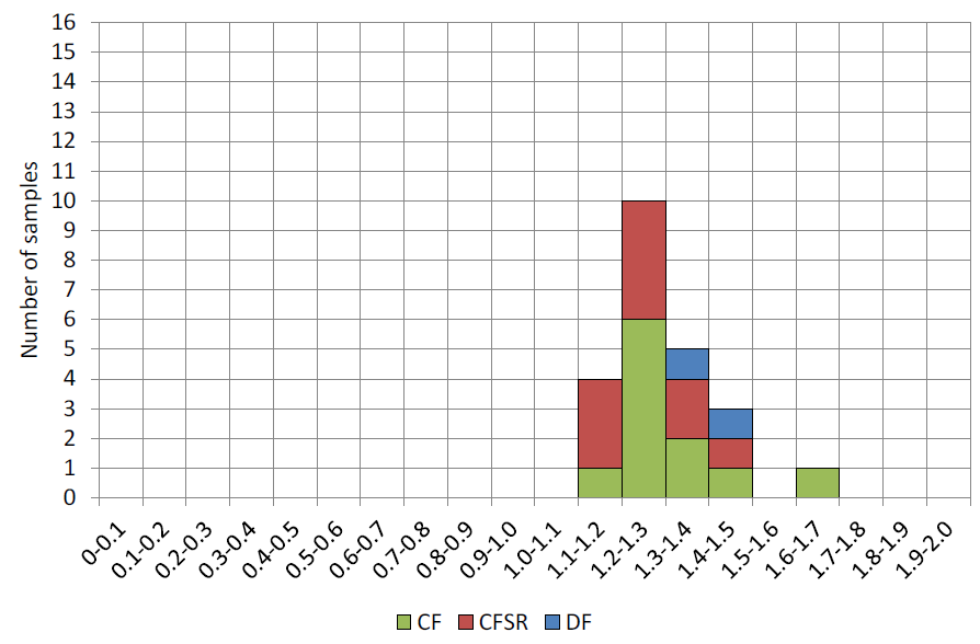
Figure 4 shows the distribution of the corner-to-flat ultimate tensile stress (strength) ratios, for which the mean for the 21 CF/CFSR sections is 1.14 and the COV is 8.8%. Again, there is a similar trend for both the CF and CFSR sections tested. The strength enhancement for the corners, relative to the flats, is much less for the ultimate stress than the yield stress.
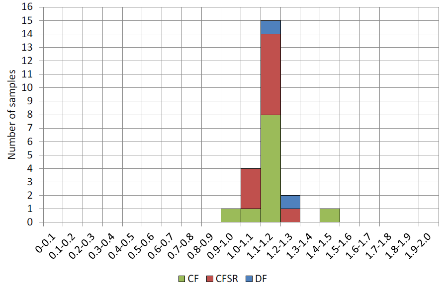
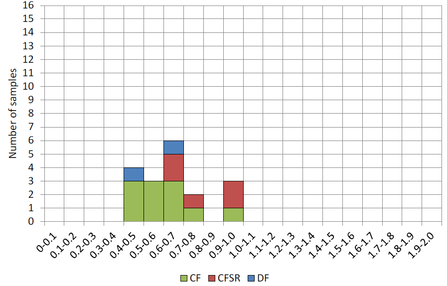
Figure 5 shows the distribution of the corner-to-flat fracture strain ratios, for which the mean of 16 CF/CFSR sections with available data is 0.65 and the COV is 24.6%. This illustrates the severe loss in ductility in the corner regions, relative the flats (which is the specified location for test samples for the producer to show compliance with the manufacturing specification). Once again, the CFSR data points are located within the spread of the CF data points.
The four CSA G40.20 HSS in Table 1 tested by Sun (2014) are of particular interest because, for both the HSS 6x6x1/2 and HSS 6x6x1/4 sizes, the CF section is the parent of the CFSR section (i.e. the latter was produced from the former by heat treatment). Although the sample size is small (two HSS), both show that heat treatment causes a small reduction in Fyc / Fyf , a small reduction in Fuc / Fuf , and a small increase in εfc /εff .
References
AISC. 2017. “Steel Construction Manual”, 15th edition, American Institute of Steel Construction, Chicago, IL.
ASTM. 2013a. “Standard Specification for Cold-Formed Welded Carbon Steel Hollow Structural Sections (HSS)”, ASTM A1085-13, American Society for Testing and Materials, West Conshohocken, PA.
ASTM. 2013b. “Standard Specification for Cold-Formed Welded and Seamless Carbon Steel Structural Tubing in Rounds and Shapes”, ASTM A500/A500M-13, American Society for Testing and Materials, West Conshohocken, PA.
ASTM. 2016. “Standard Test Methods for Tension Testing of Metallic Materials”, ASTM E8/E8M-16a, American Society for Testing and Materials, West Conshohocken, PA.
ASTM. 2017. “Standard Test Methods and Definitions for Mechanical Testing of Steel Products”, ASTM A370-17, American Society for Testing and Materials, West Conshohocken, PA.
Bruno, L. 1984. “Bolted End-Plate Splices in HSS Tension Members”, M.A.Sc. thesis, University of Toronto, Toronto, ON, Canada.
CEN. 2006. “Cold Formed Welded Structural Hollow Sections of Non-Alloy and Fine Grain Steels – Part 1: Technical Delivery Conditions”, EN10219-1:2006, European Committee for Standardization, Brussels, Belgium.
CEN. 2006. “Cold Formed Welded Structural Hollow Sections of Non-Alloy and Fine Grain Steels – Part 2: Tolerances, Dimensions and Sectional Properties”, EN10219-2:2006, European Committee for Standardization, Brussels, Belgium.
CISC. 2016. “Handbook of Steel Construction”, 11th edition, Canadian Institute of Steel Construction, Toronto, ON, Canada.
CSA. 2013. “General Requirements for Rolled or Welded Structural Quality Steel/Structural Quality Steel”, CSA G40.20-13/G40.21-13, Canadian Standards Association, Toronto, ON, Canada.
Dixon, D.A. 1983. “The Effects of Full Width Transverse Compressive Loads on RHS”, M.A.Sc. thesis, University of Toronto, Toronto, ON, Canada.
Fan, Y.-J. 2017. “RHS-to-RHS Axially Loaded X-Connections Offset Towards an Open Chord End”, M.A.Sc. thesis, University of Toronto, Toronto, ON, Canada.
August 2017