HSS-to-HSS Connection With Shear, Axial and In-Plane Moment Example
By Brady Golinski, PE; Mike Manor, PE; and Cathleen Jacinto, PE, SE
Technical Consultants, Steel Tube Institute
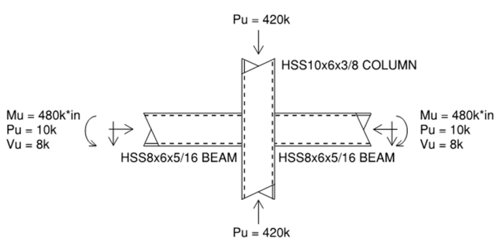
With the increasing prevalence of HSS branches connecting to HSS chords in structural applications – such as trusses, girt connections, cantilevers, and exposed steel structures – finding clear examples for HSS-to-HSS connections, especially for moment transfer, can be challenging. This example illustrates an HSS column supporting a cantilever HSS beam with a back span and an axial lateral pass-through force. The connection design follows AISC 360-16 Specification and 15th Edition Manual, with factored per LRFD load combinations.
| HSS10x6x3/8 Column/Chord: | HSS8x6x5/16 Branch: |
| ASTM A500 Grade C Fy = 50 ksi Fu = 62 ksi H = 10 in B = 6 in tdes = 0.349 in A = 10.4 in2 Sx = 27.4 in3 Zx = 33.8 in3 | Fy = 50 ksi Fu = 62 ksi Hb = 8 in Bb = 6 in tb,des = 0.291 in Ab = 7.59 in2 Sb,x = 17.1 in3 Zb,x = 20.6 in3 |
Based on geometry, this connection is classified as a cross-connection with an in-plane moment. The column is the through member and is considered the “chord,” while the beams are considered the “branches.” Since the width of the chord and branches are the same, this is a matched width connection, i.e., β = 1.0 (Bb = B). This can be considered a fully restrained (FR) moment connection per AISC terminology. FR moment connections are considered sufficiently rigid, which means the change in angle between members when load is applied is negligible. In contrast, partially restrained (PR) connections can transfer moment, but the change in angle is not negligible and must be considered in the frame analysis per AISC section B3.4b(b).
AXIAL FORCE LIMIT STATES
1. HSS Chord Plastification (Limit State Table cell L1, Truss)
This is checked with AISC 15th Edition Manual Equation 9-30.
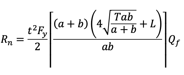
Refer to AISC 15th Edition Manual Figure 9-5(a). Since both the chord and the branch have a width of 6 inches, both a and b will equal zero, and therefore equation 9-30 is undefined. This makes sense since plastification occurs within the chord wall, but in this case, the branch has the same width. Therefore, the axial load transfers directly into the stiffer chord sidewalls instead of through the chord face, and this limit state is not applicable.
2. HSS Chord Shear Yielding (Punching) (Limit State Table Cell L2, Truss)
This is checked with AISC 15th Edition Manual equation 9-29.
Rn = 0.6Fy tp (2ceff + 2L)
This limit state occurs when the branch punches through the connecting face of the chord as a shear failure. Similar to plastification, the chord and branch have the same width in this example, which means a shear failure through chord cannot occur since the load will pass directly into the sidewalls. Therefore, this limit state is not applicable.
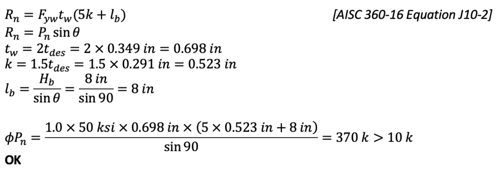
3. Local Yielding of HSS Chord Sidewalls (Limit State Table Cell L3, Truss)
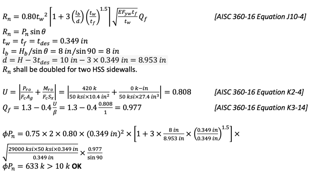
4. Local Crippling of HSS Chord Sidewalls (Limit State Table Cell L4, Truss)
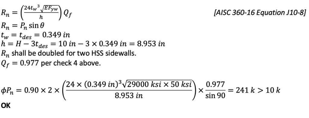
5. Local Buckling of HSS Chord Sidewalls (Limit State Table Cell L5, Truss)
6. Local Yielding of HSS Branches Due to Uneven Load Distribution (Limit State Table Cell L6, Truss)
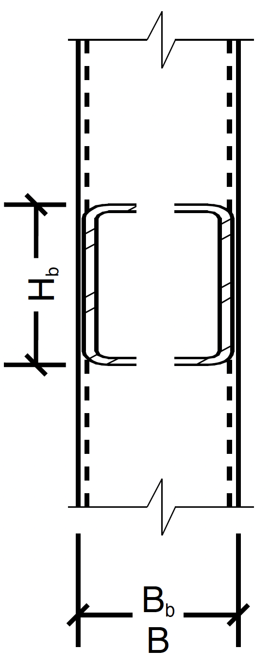
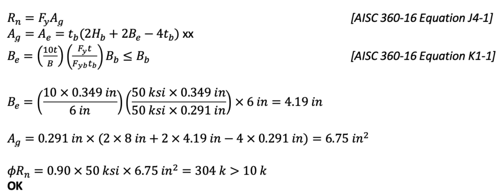
This limit state occurs because the chord face that the branch is attaching to has higher stiffness near the chord sidewalls than at the middle of the chord face. To account for this, an effective width is used for the branch walls perpendicular to the chord. Only the effective area will be counted on as shown in figure 5.
Effective area:
7. Shear Yielding of HSS Chord Sidewalls (Limit State Table Cell L7, Truss)
This limit state applies only for inclined branches. Since θ = 90 degrees in this example, there is no projected gap, and thus this limit state is not applicable.
Controlling Axial Limit State:
Local buckling of chord sidewalls: ϕRn = 241 k
MOMENT FORCE LIMIT STATES
1. Chord Wall Plastification (Limit State Table Cell F1, Moment)
This is checked with AISC 15th Edition Manual Equation 9-32.

Referring to AISC 15th Edition Manual Figure 9-5(b), T = B and c = Bb. Since T – c = 0 will be in the denominator, equation 9-32 is undefined. Similar to item A1 under the axial section above, the force will transfer directly into the chord sidewalls, and therefore this limit state does not apply.
2. HSS Chord Shear Yielding (Punching) (Limit State Table Cell F2, Moment)
This is another limit state that checks the connecting face of the HSS chord. Since this is a matched connection where the chord and branch widths are equal, this limit state does not apply. See item 2 in the axial section above for similar discussion.
3. Local Yielding of HSS Chord Sidewalls (Limit State Table Cell F3, Moment)
Rn = Fyw tw (5k + lb ) [AISC 360-16 Equation J10-2]
tw = k = tdes
lb = Hb
Mn = Rn × moment arm
moment arm = 0.5(Hb + 5k) = 0.5 × (8 in + 5 × 0.349 in) = 4.87 in
ϕMn = 1.0 × 50 ksi × 0.349 in × (5 × 0.349 + 8 in) × 4.87 in = 829 k – in > 480 k – in
OK
4. Local Buckling of HSS Chord Sidewalls (Limit State Table Cell F5, Moment)
Buckling of the sidewalls is a limit state that is only applicable to matched width (β=1.0) cross-connections when the moment is equilibrated by each branch of the cross-connection. The strength of the moment connection is increased by yielding in the adjacent tensile region. The hybrid compression buckling and tension-yielding behavior is accounted for with a local yielding check using a reduced yield strength of 0.8Fy with the same equation variable values as local yielding in moment section 3 above.
Rn = Fyw tw (5k + lb ) [AISC 360-16 Equation 10-2]
Use ϕMn from moment check 3 above.
ϕMn = 0.8 × 829 k – in = 663 k – in > 480 k – in
OK
5. Local Yielding of Branches Due to Uneven Load Distribution (Limit State Table Cell F6, Moment)
Mn = Mp = FyZ [AISC 360-16 Equation F7-1]
Z = Znet

This limit state occurs because the chord face that the branch is attaching to has higher stiffness near the chord sidewalls than at the middle of the chord face. Thus, the load is passed through the effective portions of the branch and an effective branch Zb is used in this equation, Zb,net (see Figure 6). A modification and derivation of this can be found in the paper “Stepped HSS T- and Cross-Connections Under Branch In-Plane and Out-of-Plane Bending” by Dr. Jeffrey Packer, available on the STI website. The following equation can be found there:

Controlling Moment Limit State:
Local buckling of chord sidewalls: ϕMn = 663 k – in > Mu = 480 k – in OK
AXIAL AND MOMENT INTERACTION

Therefore, this HSS-to-HSS moment connection is adequate to transfer the shear, axial and in-plane moment demand.
(NOTE: The zero term in the equation above reflects that there is no out-of-plane moment component in this example.)
February 2023
Utilizing Technology, Expertise and Communication for Better Connection Design Outcomes
Jerod Hoffman and Eric Corwin at Meyer Borgman Johnson talk with us about adapting emerging technologies within their steel connec…
ASCE 360-16 Limit State Tables
STI created Limit State Tables to help designers navigate the significant changes to Chapter K in the AISC 360-16 Specification. T…
Wide-Flange Beam to HSS Column Shear Connections and Applicable Limit States
Many of the same connections that are used for wide flange members can also be used for HSS members with occasional variations.