HSS Poles
By Jeffrey A. Packer
Bahen/Tanenbaum Professor of Civil Engineering, University of Toronto, Ontario, Canada
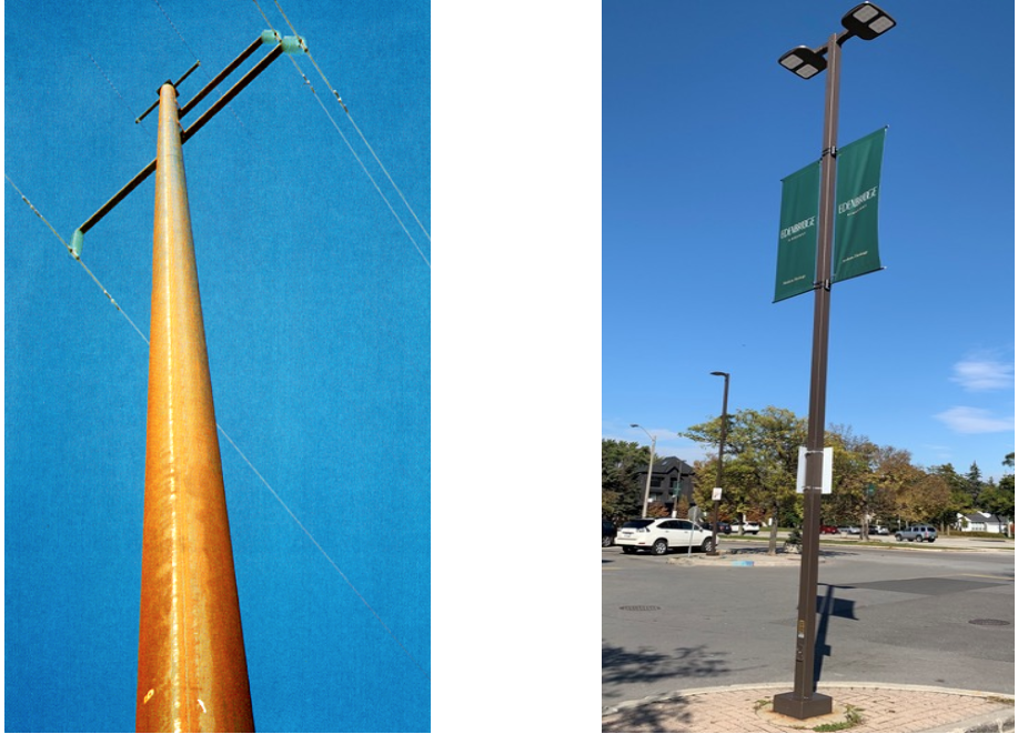
Tubular steel sections are commonly used as cantilevered structural members to support electricity distribution lines, cellular phone equipment, road and highway signs, lighting and luminaires, traffic signals, advertising boards, and in a host of similar monopole applications (Figure 1). The structural design of such poles is normally based on consideration of the strength, serviceability and fatigue limit states under all applicable load combinations. For the strength limit state, the pole needs to be designed for axial load and bending, including P-Δ effects, with moment amplification due to second-order effects. For strength-critical designs, square/rectangular HSS, round HSS, tapered round and polygonal (multisided) tubes have all been used. Fatigue considerations arise with welded attachments to poles, such as base plates. AISC 360 Appendix 3 on Fatigue (AISC 2016) does not cover welded details such as hollow sections-to-base plates, and AWS D1.1 Clause 9 on Tubular Structures (AWS 2015) covers the fatigue of round-to-round welded T-, Y- and K-connections based on offshore practice for tubulars. Guidance for the design of monopoles, however, is given by AASHTO (2015).
AASHTO
Detailed design provisions are provided for steel structural supports for highway signs, luminaires and traffic signals (AASHTO 2015), but for hollow sections, these only cover round and multisided shapes. Clause 5.6.2 specifies that multisided tubular sections shall have a minimum number of sides, n, where
n≥√5D
Equation 1
D is the outside distance from flat side to flat side of a multisided tube (in.) and n has a minimum value of 8. The Commentary states that square or rectangular sections are susceptible to early fatigue cracking, leading to poor fatigue performance, hence these sections should not be used for highway sign, signal and high-level luminaire support structures (Dexter and Ricker 2002). Increasing the number of sides and/or increasing the internal bend radius improves the fatigue performance of multisided sections (Roy et al. 2011), and since pole members are frequently galvanized, larger corner radii also reduce the possibility of liquid metal embrittlement during hot-dip galvanizing. A minimum bend radius of five times the tube wall thickness mitigates the possibility of such embrittlement according to AASHTO (2015). Due to the prohibition of square and rectangular HSS for highway signs and associated structures, such shapes are predominantly used for low-level poles in urban situations (e.g., Figure 1[b]).
Fatigue Design of Welded Base Plate Connections
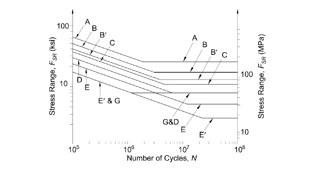
High-cycle fatigue design of base plate connections is normally performed using the nominal stress method in conjunction with a classification for the base plate welded joint detail. Accurate load spectra for defining fatigue loads are hard to prescribe with environmental loadings, so faced with this dilemma, engineers typically resort to an “infinite fatigue life” design. This involves keeping the maximum elastic normal stress range below a constant amplitude fatigue threshold, FTH, which corresponds to the horizontal line(s) in Figure 2. HSS fillet-welded to a base plate, with the weld transverse to the direction of cyclic stress, are relegated to the lowest fatigue category, E‘ in Figure 2, for which FTH has a very low value of 2.6 ksi (18 MPa). This also corresponds to the lowest fatigue threshold stress in Tables 11.9.3.1-1 and C11.9.3.1-1 of AASHTO (2015). The infinite life fatigue design approach should ensure that a structure performs satisfactorily for its design life to an acceptable level of reliability without significant fatigue damage and propagation of cracks (AASHTO 2015). The fillet-welded HSS-to-base plate fatigue detail is specifically included in the Canadian steel design code (CSA 2019), and experimental research on such connections (Mashiri et al. 2002) has confirmed the linearly decreasing low-cycle portion of the fatigue design S–N “curve.” (A design line with a slope of m = -3, passing through FSR= 6.3 ksi [43 MPa] at 2 million cycles, was obtain from experiments.) The fatigue threshold value of 2.6 ksi (18 MPa) could not be confirmed because of the very long testing time required and is instead inferred from experience.
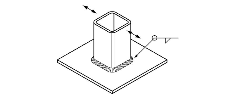
One of the causes for low fatigue resistance in many square/rectangular HSS welded connections in practice is the improper welding procedure used. In dynamically loaded, welded HSS connections, it is extremely important that weld starts and stops, which tend to introduce weld discontinuities, are not made at the so-called “hot spots” of stress concentration.
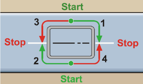
For a square/rectangular HSS welded to a flat surface, the points of stress concentration occur at the 4 HSS corners. Thus, weld starts/stops should occur along the flat sides of the HSS, as shown in Figure 4, which is contrary to how welders tend to perform such welding. (As an aside, the weld start/stop locations are not critical for statically loaded welded joints.) Fatigue experiments on HSS-to-base plate connections under bending (Mashiri et al. 2002) have also confirmed that, even with well-inspected welded joints before testing, cracking will initiate at the weld toe to the HSS at the corner of the HSS, and then propagate toward the middle of the HSS width.
Base Plates and Anchor Rods
AASHTO (2015) points out that the fatigue resistance of tube-to-base plate connections is a function of the relative stiffness of the tube and the plate, with the plate flexibility having a large influence on stress amplification in the tube wall adjacent to the weld toe. Thus, a relatively thick and stiff base plate is an effective means of increasing the connection fatigue resistance. Roy et al. (2011) also showed, by laboratory tests, that groove-welded connections had superior fatigue lives compared to fillet-welded connections in identical structures. AASHTO (2015) Table 5.6.3-1 hence prescribes a minimum base plate thickness, to counter fatigue, of 1.5 inches (for D ≤ 8 inches) or 2.0 inches (for D > 8 inches), where D is the pole diameter or depth. For the base of a high-mast lighting tower, a minimum of eight anchor rods is specified. Beyond the above minima for AASHTO highway structures, AASHTO recommends AISC Design Guide No. 1 (Fisher and Kloiber 2006) for design of the base plate and anchor rods.
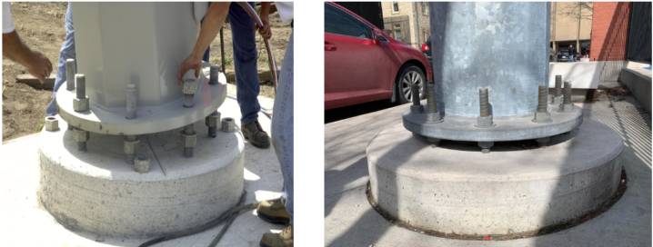
Two types of anchoring are in popular use for base plates. For smaller poles especially, the base plate is founded directly on concrete, or grout is used to infill between the base plate and the foundation. In this case, a single nut is used above the base plate on each anchor rod. Alternatively, especially for larger poles, a double-nut connection may be used as shown in Figure 5, with the lower nuts used to plumb the pole. For double-nut connections, AASHTO (2015) stipulates that bending stresses in the anchor rods may be ignored if the clear distance between the bottom of the leveling nuts and the top of the concrete foundation is minimal, which is defined as less than or equal to one bolt diameter. For gaps greater than this, designers are referred to recent work by Cook et al. (2013).
References
AASHTO. 2015. “LRFD Specification for Structural Supports for Highway Signs, Luminaires and Traffic Signals,” American Association of State Highway and Transportation Officials, Washington, D.C., with 2017, 2018 and 2019 Interim Revisions.
AISC. 2016. “Specification for Structural Steel Buildings,” ANSI/AISC 360-16, and Commentary, American Institute of Steel Construction, Chicago, IL.
AWS. 2015. “Structural Welding Code – Steel,” AWS D1.1/D1.1M:2015, 23rd edition, American Welding Society, Miami, FL.
Cook, R.A., Prevatt, D.O. and McBride, K.E. 2013. “Steel Shear Strength of Anchors With Stand-Off Base Plates,” Florida Department of Transportation Research Report BDK75-49, Tallahassee, FL.
CSA. 2019. “Design of Steel Structures,” CSA S16:19, Canadian Standards Association, Toronto, ON.
Dexter, R. and Ricker, M. 2002. “Fatigue-Resistant Design of Cantilever Signal, Sign and Light Supports,” NCHRP Report No. 469, Transportation Research Board, National Research Council, Washington, DC.
Fisher, J.M. and Kloiber, L.A. 2006. “Base Plate and Anchor Rod Design,” Steel Design Guide No. 1, 2nd edition, American Institute of Steel Construction, Chicago, IL.
Mashiri, F.R., Zhao, X.L. and Grundy, P. 2002. “Fatigue Tests and Design of Thin Cold-Formed Square Hollow Section-to-Plate T-Connections under In-Plane Bending,” Journal of Structural Engineering, American Society of Civil Engineers, Vol. 128, No. 1, pp. 22-31.
Roy, S., Park, Y.C., Sause, R., Fisher, J.W. and Kaufmann, E.K. 2011. “Cost-Effective Connection Details for Highway Sign, Luminaire and Traffic Signal Structures,” NCHRP Doc. 176 (Final Report for NCHRP Project 10-70), Transportation Research Board, National Research Council, Washington, D.C.
November 2019