HSS Limit State: Plastification
By Mike Manor, PE, MLSE
FORSE Consulting, Technical Consultant to the Steel Tube Institute
Intro
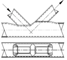
At first glance, some of the limit states required for the design of HSS connections can be a bit confusing if you are unfamiliar with HSS connection design. Some confusion stems from the terminology, which isn’t always defined specifically within the codes or other reference books. One in particular that is unique to HSS is the limit state of plastification. The resistance equation given by the code is easy enough to crunch the numbers but little else is given. The definition in the 15th Edition AISC Steel Construction Manual is “plastification: In an HSS connection, limit state based on an out-of-plane flexural yield line mechanism in the chord at a branch member connection.” What does all of that mean?

(15th edition AISC Manual of Steel Construction)
Research
Researching the plastification limit state leads one to a surprising place. Yield line theory was originally conceived for concrete slabs by Danish engineer and researcher K. W. Johansen in the 1940s. With further research and refinement by many people through the 20th century, the experimental and theoretical results matched really well and were slightly on the conservative side. The yield line design publication “Practical Yield Line Design” also notes that yield line theory works well for sizing steel plates in bolted connections for out of plane forces since steel is good at plastic redistribution of stresses. Design procedures for extended end plates commonly use the yield line theory, therefore it makes perfect sense that a similar methodology could be applied to HSS walls under out of plane loading. When one thinks about a load perpendicular to a thin HSS wall from an engineering mechanics standpoint, it does make sense that the HSS wall and a thin concrete slab would behave similarly.
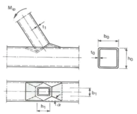
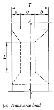
The main idea behind yield line theory is that steel is an elastic material which stretches when stressed but will return to its original size and length when unloaded. However, once it reaches its yield point, the steel will no longer return to its original state and will be permanently deformed when unloaded. This state is called plastic behavior. Thus, plastification is the design limit state that occurs when steel is stressed beyond its yield strength. A good approximation for the flexural capacity of plastification is through a yield line mechanism. Figures 2 and 3 show examples of yield line patterns. The dashed lines represent lines along which yielding will likely occur.

(CIDECT DG 3 Second Edition)
In a T-connection, where a connection is made at 90 degrees to an HSS chord wall under out-of- plane loading, there are two main failure modes for the HSS wall being connected to. One based on shear and another based on flexure. Let us take a look at the shear case first. When a plate is connected to the face of an HSS, the contact area of that plate is relatively small which will consequently have a small shear perimeter. Therefore, the plate would be much more likely to have a shear yielding failure by “punching” through the face of the HSS. However, when the T-connection is changed from a plate to another HSS shape, the total area of HSS chord wall engaged is significantly larger and thus has a much larger shear perimeter. This means that the likeliness of shear controlling the capacity goes down and likeliness of flexure controlling goes up. The question then becomes: “How is that HSS face going to fail in flexure?” This is where the yield line analysis comes into play. Yield line analysis looks at all of the possible combinations of lines where bending of the HSS wall will occur to determine which yield line combination will produce the lowest capacity. The next step in yield line analysis is to apply the virtual work analysis method. The key is that the external energy induced by the load onto the HSS face at failure must be equal to the internal energy that is dissipated along the yield lines through the rotation of the steel. In other words, the amount of work required to bend the steel is equal to the work produced by the load. To find this balance, the correct length and geometry of the yield lines must be found. Along these lines, yielding occurs followed by stress redistribution otherwise known as “plastification”.

(AISC 15th Edition Steel Construction Manual)
Fortunately, this process is incorporated into the equations listed in the 15th Edition Steel Construction Manual making our lives much easier. One last item to be aware of is that the look and the locations of these plastification equations have changed from AISC 360-10 and the 14th Edition Steel Construction Manual to AISC 360-16 (15th Edition). In AISC 360-10, the plastification equations are located within the Specification and the limit state tables as part of Chapter K. However, many of the capacity equations have been removed from AISC 360-16, Chapter K and instead must be inferred through a combination of equations in Chapter J and Part 9 of the 15th Edition Steel Construction Manual. Once the variables for HSS members are placed into the appropriate equations of 360-16, along with some algebraic manipulation, many of the equations in the 360-10 Chapter K tables can be reproduced in the same form. Fortunately, a forthcoming Limit State Table from STI will be listing the equations and variables necessary to evaluate the capacity for each limit state.
Conclusion
It is always best to have at least a basic understanding of what each limit state equation is checking when performing connection designs. Sometimes the definitions given don’t always fully explain what the terminology means. Fortunately for this case, plastification is simply a matter of finding the flexural plastic capacity of the face of an HSS member. The reality is that plastification is just a fancy sounding word for what structural engineers do every day when designing steel.
References
AISC. 2010a. “Steel Design Guide Series 24: Hollow Structural Section Connections”, American Institute of Steel Construction, Chicago, IL.
AISC. 2010. “Specification for Structural Steel Buildings”, ANSI/AISC 360-10, American Institute of Steel Construction, Chicago, IL.
AISC 2011. “Steel Construction Manual, Fourteenth Edition”, American Institute of Steel Construction, Chicago, IL.
AISC. 2016. “Specification for Structural Steel Buildings”, ANSI/AISC 360-16, American Institute of Steel Construction, Chicago, IL.
AISC. 2017. “Steel Construction Manual, Fifteen Edition”, American Institute of Steel Construction, Chicago, IL.
CIDECT 2009. “Design Guide 3: For Rectangular Hollow Section (RHS) Joints Under Predominantly Static Loading 2nd Edition”, Comite International pour le Developpement et l’Etude de la Construction Tubulaire.
2004. “Practical Yield Line Design”, The Concrete Centre, Surrey.
July 2018