HSS Connections with Rotated Members
By Jeffrey A. Packer
Bahen/Tanenbaum Professor of Civil Engineering, University of Toronto, Ontario, Canada
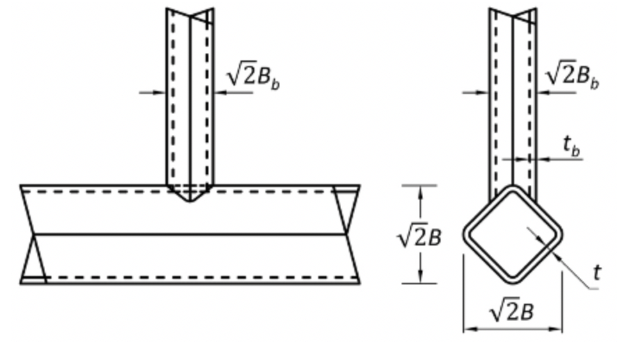
Architects are continually exploring ways to make interesting and aesthetic structures with HSS. One way is to rotate square HSS branch and/or chord members by 45 degrees about their member axes. This can significantly complicate the fabrication process, but it does produce connections that are both novel and generally stronger than their counterparts with non-rotated members. The three options available are illustrated in Figure 1. Rotation of the chord produces a “bird-beak connection”, so-called because of the end shape of the branch member. This necessitates very careful profiling of the web member ends, particularly where the outside corner radii are large, such as with thick-walled chords. Corner radii vary considerably between HSS sizes, between manufacturers, and even between the four corners on a particular length of HSS. Rotation of both the branch and the chord, see Figure 1(c), produces a particularly eye-catching connection, as shown in Figure 2. This “diamond-bird-beak connection” has been used in the Minneapolis Convention Center roof as well as the Minneapolis/St. Paul Twin Cities Airport skyway.


Square HSS Connections with Rotated Branches

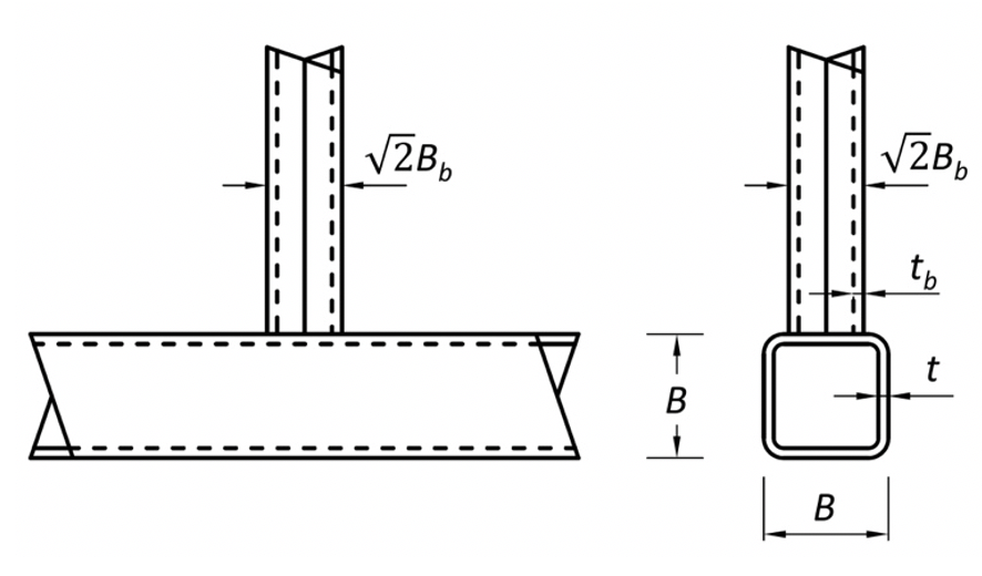
Rotation of just the branch (or branches) of a connection by 45° about the member axis produces a connection with a larger effective branch-to-chord width ratio, of approximately √2(Bb/B), as shown in Figure 3. The connection strength is thus enhanced, relative to the “traditional” connection without branch rotation. This has been confirmed by experiments on branch-rotated (BR) T-connections (Bae et al., 2006). The footprint of the branch on the chord is similar to that of a round HSS branch of diameter √2Bb, so it is suggested that BR connections be treated as round-to-rectangular HSS connections with a branch diameter of Db=√2Bb and the same branch thickness. Round-to-rectangular HSS connections can in turn be designed by transforming them into equivalent (traditional) rectangular hollow section (RHS) connections, by using a “branch conversion method” (Packer et al., 2007). This entails replacing Bb and Hb in RHS connection available strength formulas (e.g. AISC, 2016; Packer et al., 2010) with Db=√2Bb, and then multiplying the resulting connection available strength by π/4 (Packer, 2016). The effect of this double conversion, applied to the chord face plastification limit state for gapped K-connections as an example, is to increase the strength of the connection (BR relative to traditional) by √2(π/4), or by 11%. This increased resistance is in line with comparative tests on T-connections governed by the chord face plastification failure mode (Bae et al., 2006).
Square HSS Connections with Rotated Chord
By framing onto a corner of the HSS chord member a high connection strength and stiffness is achieved, regardless of the web-to-chord member width ratio. The chord crown position is a stiff HSS corner which resists chord plastification into the diamond shape shown in Figure 4(a).
Square-bird-beak (SBB) connections, so-called because the branch remains square but the chord is rotated (Figure 4), have been the subject of a numerical study by Chen and Wang (2015). For T-connections, for which the general failure mode was chord face plastification, Chen and Wang determined a correction factor to be applied to the available strength of a traditional RHS-to-RHS connection, but the factor is questionable. Since the strength of SBB connections should be somewhat higher than their traditional counterparts, a conservative design approach would be to consider SBB connections as traditional HSS connections (with a non-rotated chord) and use appropriate formulas from AISC (2016) and AISC Design Guide No. 24 (Packer et al., 2010). Attention must also be paid to appropriate end preparation (beveling) of the branch at the saddle point.

Square HSS Connections with Rotated Chord and Rotated Branches
Ono et al. (1991) were the first to perform experimental research on square HSS T- and K-connections of this diamond bird-beak (DBB) type, with all members rotated by 45o. They found that these connections are not only much stronger than their conventional (non-rotated) connection counterparts, but are also generally stronger than equivalent round HSS connections with members having the same cross-sectional area. (The cases in which equivalent round HSS connections are stronger are likely to occur for high web-to-chord width ratios and low B/t ratios). With these connections, shown in Figure 5, the force from the branch is primarily applied at the ridge of the chord, as if it were two concentrated loads at the intersecting corner points. The connection is relatively ductile and chord plastification is the dominant failure mode.

T- and Cross-Connections
The nominal ultimate strength of a DBB T-connection is given by (Ono et al., 1991; Ishida et al., 1993):

where Fy is the yield stress of the chord member, t is the design thickness of the chord, Bb is the regular width of the branch member, and B is the regular width of the chord member. Because of the similarity of this connection type to a round-to-round HSS T-connection, as also observed by Owen et al. (1996), the chord stress factor Qf can be taken as that for round HSS connections in AISC 360-16 Eq. (K2-3) (AISC, 2016) and AISC Design Guide No. 24 (Packer et al., 2010). To obtain the connection available strength from Eq. (1), a resistance factor of φ = 0.9 is recommended. Eq. (1) is empirically derived from test data, so one should be careful to ensure that it is only applied within the approximate bounds of the parameter ranges examined in the tests (Packer and Henderson, 1997; Packer et al., 2009), which are: 16 ≤ B/t ≤ 42 and 0.3 ≤ Bb/B ≤ 1.0. Since tubular T-connection capacity and behavior is very similar to tubular Cross-connection capacity, Eq. (1) can also be applied to DBB Cross-connections.
Further research on DBB T- and Cross-connections has followed (Davies and Kelly, 1995; Davies et al., 1996; Owen et al., 2001; Pena and Chacon, 2014; Chen and Wang, 2015), but this has not led to recommendations that are a demonstrable improvement.
Gapped K-Connections
The nominal ultimate strength of a DBB gapped K-connection is given by (Ono et al., 1991):

where Fy, t, B and Qf are defined above for T- and Cross-connections, and θ is the branch-to-chord acute angle. The term α represents the fraction of the chord cross-sectional area that is effective and, although given graphically by Ono et al. (1991), can be calculated conservatively by the linear approximation:

To obtain the connection available strength from Eq. (2), a resistance factor of φ = 0.9 is recommended. Eq. (2) is empirically derived from test data and valid within: 16 ≤ B/t ≤ 44 and 0.2 ≤ Bb/B ≤ 0.7. Also, all test specimens had branch angles of 45o, so caution should be exercised for K-connection branches significantly different to this. A slightly more accurate version of Eq. (2) was proposed by Ishida et al. (1993), using a regression analysis fit to the test data, but is far more complex. DBB overlapped K-connections have also received some attention (Kelly, 1998; Davies et al., 2001), but profiling of the branch member ends then becomes an even greater concern.
References
AISC, 1997. “Hollow Structural Sections Connections Manual,” American Institute of Steel Construction, Chicago, IL.
AISC, 2010. “Specification for Structural Steel Buildings,” ANSI/AISC 360-10, American Institute of Steel Construction, Chicago, IL.
AISC, 2011. “Steel Construction Manual, Fourteenth Edition,” American Institute of Steel Construction, Chicago, IL.
AISC, 2016. “Specification for Structural Steel Buildings,” ANSI/AISC 360-16, and Commentary, American Institute of Steel Construction, Chicago, IL.
AISC, 2017. “Steel Construction Manual, Fifteenth Edition,” American Institute of Steel Construction, Chicago, IL.
McCormick, J. 2016. “Square and Rectangular HSS-to-HSS Moment Connections,” Steel Tube Institute, September.
Olson, K. 2020. “CJP HSS Welds: Be Informed Before You Specify,” Steel Tube Institute, May.
Packer, J.A., Wardenier, J., Zhao, X.L., van der Vegte and Kurobane, Y. 2009. “Design Guide for Rectangular Hollow Section (RHS) Joints under Predominantly Static Loading,” CIDECT Design Guide No. 3, 2nd edition, CIDECT, Geneva, Switzerland, ISBN 978-3-938817-04-9.
Packer, J., Sherman, D. and Lecce, M. 2010. “Hollow Structural Section Connections,” Steel Design Guide No. 24, American Institute of Steel Construction, Chicago, IL.
Packer, J.A. 2012. “Welding of Hollow Structural Sections,” Steel Tube Institute, March/April.
Packer, J.A. 2019. “Stepped HSS T- and Cross-Connections Under Branch In-Plane and Out-of-Plane Bending,” Steel Tube Institute, March.
STI, 2020. “Limit State Table,” Steel Tube Institute.
August 2021