Gusset Plate-to-HSS Column Connections Under Eccentric Brace Loads
By Jeffrey A. Packer
Bahen/Tanenbaum Professor of Civil Engineering, University of Toronto, Ontario, Canada
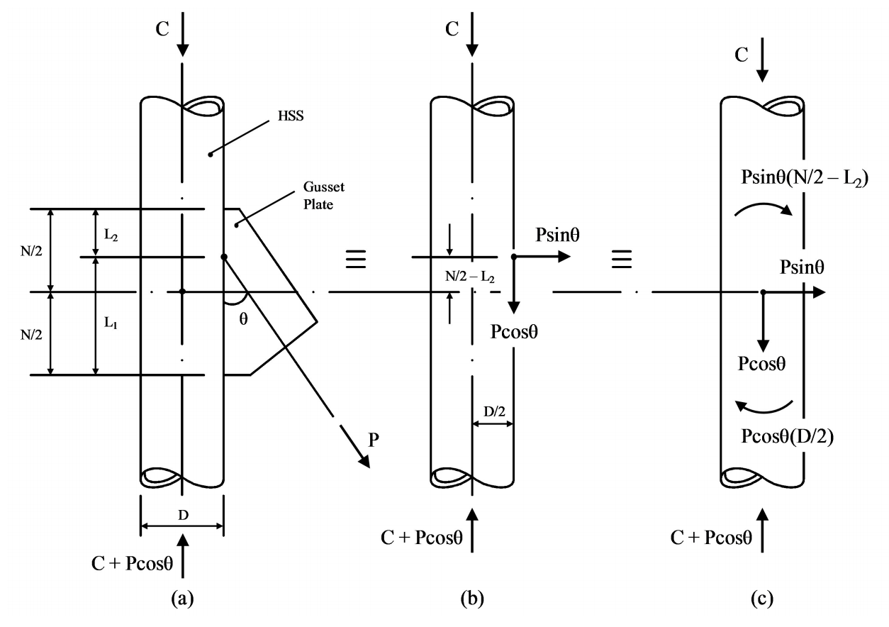
A frequent column connection arises, in braced steel frames, in which a diagonal bracing member applies an axial force to a longitudinal gusset plate that is in turn welded to an HSS column. Often the gusset plate is not centered on the work-line of the brace, as shown in Figure 1(a) for a round HSS column. Such an arrangement produces both an axial load and a moment on the gusset plate, since L1 and L2 are not equal. In order to check the connection capacity using AISC 360-10 Chapter K (AISC, 2010) various interpretations are possible, but one can initially resolve the inclined brace force into vertical and horizontal components, at the HSS face, as shown in Figure 1(b). The horizontal component, PsinӨ, can then be transferred to the center of the plate, with the addition of a couple PsinӨ(N/2 – L2), as shown in Figure 1(c). Similarly, the vertical component, PcosӨ, could be transferred to the center of the column, with the addition of a couple PcosӨ(D/2). Thus, the total moment at the column connection would be:
M = Psinθ(N/2 — L2) + Pcosθ(D/2)
Equation (1)
For a round HSS column, as illustrated in Figure 1, the connection resistance could then be checked by using a linear interaction of the axial force resistance and in-plane bending resistance, of the longitudinal plate connection, from AISC (2010):
Psinθ /(фRn) + M/(фMn) ≤ 1.0
Equation (2)
where ф = 0.90, Rn is given by equation (K1-2) of Table K1.1, M is given by equation (1) above, and Mn is given in Table K1.1 for in-plane plate bending. (Table K1.1 does not give any nominal flexural strength, Mn, for a longitudinal plate, under out-of-plane plate bending because – as one would imagine – it is extremely weak under such loading.)
Equation (K1-2) does contain the factor Qf, defined by equation (K1-5), which accounts for the effect of chord (or column) normal stress acting on the connecting surface of the HSS, and is ≤ 1.0 if the connecting face is subject to compressive normal stress. Qf in turn is dependent on the column face utilization, U, defined by equation (K1-6). However, one should note that U is calculated for the side of the connection that has the lower compression stress. (Although counter-intuitive, this stems from formulas produced in Japan that were subsequently adopted by IIW (1989) and then by AISC.) Thus, for equation (K1-6), and for the force arrangement shown in Figure 1, the compressive stress in the connecting face above and below the connection would need to be calculated. Above the gusset-plate connection, Pro = C and – if half of the moment, M, is distributed to the column above the connection – Mro = M/2.
For a square or rectangular HSS column, the symbol D in equation (1) and in Figure 1 needs to be replaced by the symbol B or H (as applicable). The connection resistance can again be checked by using a linear interaction of the axial force resistance and in-plane bending resistance, per equation (2), but using ф = 1.00 and Rn given by equation (K1-12) of Table K1.2. M is again given by equation (1) but a solution for Mn, for in-plane plate bending, is not available in Table K1.2. Instead, one should use the solution for HSS-to-HSS T-connections under branch in-plane bending, given by equation (K3-6) in Table K3.2, and consider the plate branch as a long, thin, rectangular HSS branch where the plate length, N = Hb and the plate thickness = Bb. Equation (K3-6) is simply a yield line solution for a plastic collapse mechanism in the HSS connecting face, so this formula for Mn and the associated ф = 1.00 are quite appropriate, even though the plate branch is unlikely to be technically in compliance with Table K3.2A (which requires Bb/B ≥ 0.25, due to that being the lower limit of validation for HSS-to-HSS connections). Equations (K1-12) and (K3-6) both contain a Qf factor based on U determined on the side of the connection with the lower compression stress too.
One might have noticed that square and rectangular HSS-to-HSS truss connections, under branch axial loading, which have connection resistances given in Table K2.2, are subject to a Qf factor based on U determined on the side of the connection with the higher compression stress. (See the “Functions” part of Table K2.2, where U is not strictly identical to equation (K1-6)). A more consistent treatment of Qf factors for all HSS connections has recently been proposed (Packer et al., 2009), and adopted by ISO (2013), but this is not incorporated in the current AISC Specification (AISC, 2010).

References
AISC. 2010. “Specification for Structural Steel Buildings”, ANSI/AISC 360-10, American Institute of Steel Construction, Chicago, IL.
IIW. 1989. “Design Recommendations for Hollow Section Joints – Predominantly Statically Loaded”, 2nd edition, IIW Doc. XV-701-89, International Institute of Welding, Paris, France.
ISO. 2013. “Static Design Procedure for Welded Hollow-Section Joints – Recommendations”, ISO 14346:2013(E), International Standards Organisation, Geneva, Switzerland.
Packer, J. A., Wardenier, J., Zhao, X.-L., van der Vegte, G.J. and Kurobane, Y. 2009. “Design Guide for Rectangular Hollow Section (RHS) Joints under Predominantly Static Loading”, CIDECT Design Guide No. 3, 2nd edition, Comité International pour le Développement et l’Étude de la Construction Tubulaire, Geneva, Switzerland, ISBN 978-3-938817-04-9.
February 2014