Full-Capacity Welds: CJP vs. Fillet vs. Fillet-Reinforced PJP
By Jeffrey A. Packer
Professor, Department of Civil & Mineral Engineering, University of Toronto, Ontario, Canada
November, 2024
There are numerous situations in practice where a weld is required to develop the full strength of the element to which it is attached. In such cases, designers are tempted to specify complete joint penetration (CJP) groove welds. However, these are seldom necessary and alternatives such as fillet welds, or partial joint penetration (PJP) groove welds with a fillet reinforcement, are alternatives that are still able to deliver “full-capacity joints” (where the weld resistance matches the attached HSS wall yield resistance).
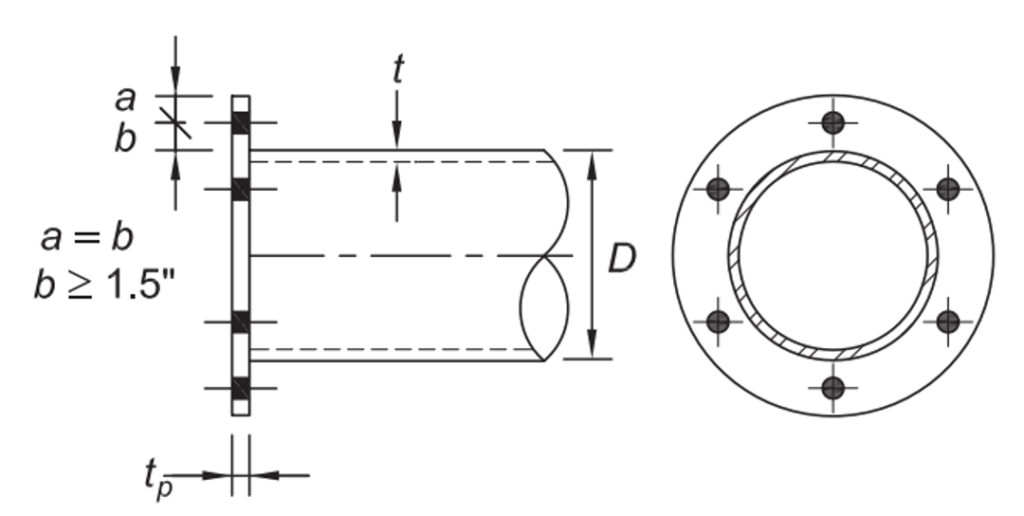
As an illustration, a common method of splicing HSS together, that involves bolting outside the members, is the bolted end-plate connection (Figure 1). The design method for this round HSS connection type in AISC DG24 (Packer and Olson, 2024) produces a flexible end plate that imposes considerable local bending on the HSS-to-plate weld, hence this weld needs to be designed to develop the HSS wall strength. In the following, this example will be used to demonstrate the design of the three available weld types: CJP, fillet, and fillet-reinforced PJP.
CJP Welds
Welds to a HSS wall are inherently single-sided, since welds cannot be made inside the HSS. Steel backing – whenever possible – should be used with a root detail that facilitates sound placement of the filler metal and, in general, the backing needs to be continuous for the length of the joint (AWS D1.1 Clause 7.9.1.2). The backing may be left in place, if the weld is statically loaded; under cyclic loading, backing cannot be left in place and the welding must be performed from one side without backing – an even more-difficult procedure. The fit-up, skill and welder qualification requirements for CJP welds make them difficult and expensive, so the specification of a CJP weld should only be an exceptional case.
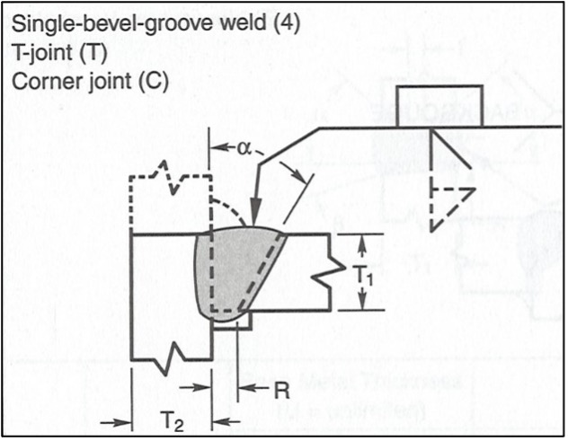
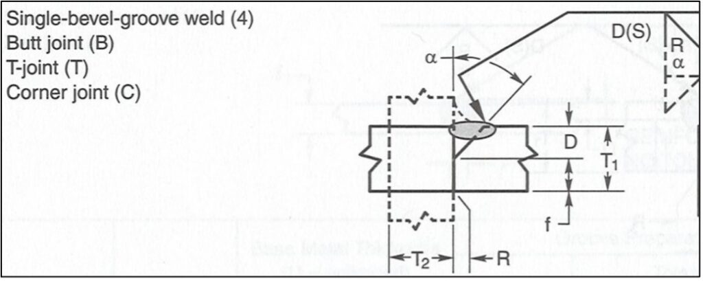
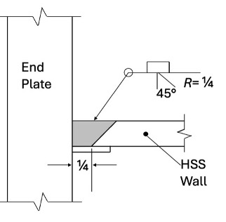
CJP groove weld requirements for HSS-to-HSS T-, Y- and K-connections are given by AWS D1.1 Clause 10.10 and in the figures referenced. For the end-plate example in Figure 1, a prequalified CJP welding procedure specification (WPS) for this T-joint can be obtained from Figure 5.1 of AWS D1.1 Clause 5, or Table 8-2 in the AISC Manual (AISC, 2023), which is shown in Figure 2. Joint details vary with the welding process, but for FCAW or GMAW (Joint designation TC-U4a-GF) a suitable groove preparation for all-position welding is achieved with a root opening of R = ¼ in. and a groove angle of α = 45o. After fit-up, tolerances still permit prequalification provided 3/16 in. ≤ R ≤ ½ in., and 40o ≤ α ≤ 55o.
As noted in AWS D1.1 Table 4.3, and also in Table J2.5 of the AISC Specification (AISC, 2022), the strength of the CJP welded joint is controlled by the base metal, providing matching filler metal is used. E70 filler metal, with a specified tensile strength of 70 ksi, is considered matching for ASTM A500 Grade C and ASTM A1085 HSS with a specified minimum yield strength of 50 ksi. Thus, the welded joint is automatically “full-capacity” and no calculations are required. For T-joints (as in Figure 1) with the backing left in place, notch-tough filler metal is required (AISC, 2022).
Fillet Welds
Fillet welds are the simplest, and generally the least-expensive, weld type. While a fillet weld can be added to a PJP groove weld to increase the PJP joint strength, the addition of a fillet weld to a CJP groove weld – while permissible for providing a more gradual transition (and a decreased stress concentration) between members or elements – cannot be used to enhance the joint strength beyond the CJP groove weld strength. The strength of fillet welds is given in Section J2.4 and Table J2.5 of the AISC Specification (AISC, 2022). Table J2.4 also specifies minimum sizes for fillet welds, but this is unlikely to govern for a fillet weld that is being designed for a full-capacity joint. Weld strength is determined by the limit state of shear rupture along the weld effective throat, regardless of the direction of loading, providing filler metal with a strength level equal to or less than matching is used. Thus, the nominal strength of a fillet weld is given by:
Rn = FnwAwekds AISC Spec. Eq. (J2-4)
where Awe = effective area of the weld, in.2
Fnw = nominal stress of the weld metal, ksi
kds = (1.0 + 0.50 sin1.5 θ) AISC Spec. Eq. (J2-5)
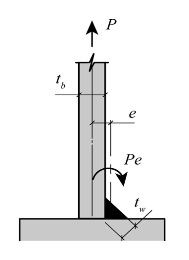
kds is a directional-strength-increase factor, which can be applied to fillet welds where strain compatibility of the various welds is considered. An exception to the use of this factor is for fillet welds to the ends of rectangular HSS loaded in tension, in which case kds = 1.0. The angle, θ, is the angle between the line of action of the required force and the weld longitudinal axis, in degrees. An explanation of the basis for this kds factor, and its application to HSS connections, is given in Chapter 3 of AISC DG24 (Packer and Olson, 2024). The reason for not allowing kds > 1 for single-sided welds to tension-loaded rectangular HSS walls is that local bending occurs about the axis of the weld, tending to open the weld at the root (see Figure 3). On the other hand, single-sided welds to tension-loaded round HSS walls display a lower tendency to suffer from this local bending effect and they achieve the expected welded joint reliability level (unlike their counterparts to tension-loaded rectangular HSS).
For a fillet weld to develop the attached HSS wall yield resistance, over a unit length of weld or wall (e.g. 1 in.), one can equate the available strength of the fillet weld to the yield resistance of the attached HSS:
φRn = φweldFnwAwekds = φHSSFy-HSSAHSS (1)
where φHSS = 0.9 and φweld = 0.75 for the case of shear on the fillet weld and Fnw = 0.60FEXX (AISC Specification Table J2.5), with FEXX being the ultimate strength of the weld metal. Thus, Eq. (1) can be simplified to:
0.75(0.60)FEXXtw(1in.)kds = 0.9Fy-HSSt(1in.) (2)
Hence,

where tw is the required fillet weld throat thickness (or effective throat) for a HSS wall thickness of t. (Note that t = tb if the connected HSS member is a branch in a HSS-to-HSS T-, Y-, Cross- or K-connection).
Fillet-Reinforced PJP Welds
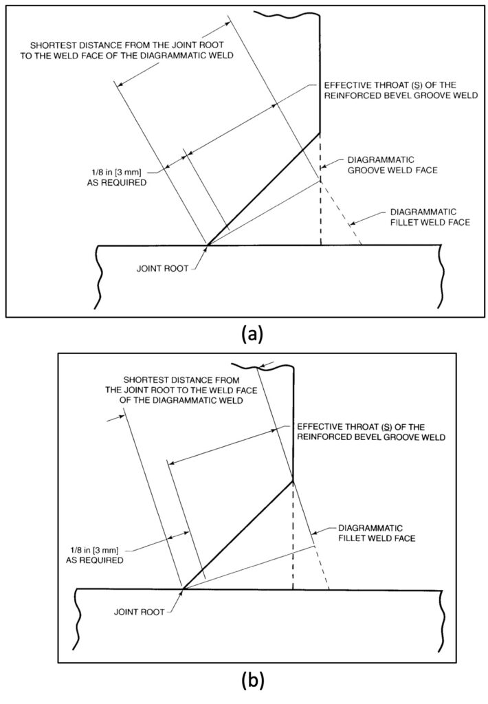
AWS D1.1 Clause 4.4.2.7 states that … “The effective throat of a combination PJP bevel groove weld and a fillet weld shall be the shortest distance from the joint root to the weld face of the diagrammatic weld minus 1/8 in. [3 mm] for any groove detail requiring such deduction”. Examples of such effective throats, for two different reinforcing fillets, are shown in AWS D1.1 Figures 4.3 and 4.4 (reproduced herein as Figure 4). The effective throat is subject to a deduction of 1/8 in., to account for lack of weld penetration to the joint root (see Figure 4), when applicable. The cases for which the deduction of 1/8 in. applies are given in AWS D1.1 Figure 5.2 for prequalified PJP groove weld joint details.
For the end-plate example in Figure 1, a prequalified PJP (or PJP + fillet) welding procedure specification (WPS) for this T-joint can be obtained from Figure 5.2 of AWS D1.1 Clause 5, or Table 8-2 in the AISC Manual (AISC, 2023), which is shown in Figure 5. Joint details vary with the welding process, but for FCAW or GMAW (Joint designation BTC-P4-GF) and a HSS wall thickness, T1 ≥ ¼ in., a suitable groove preparation on the HSS for welding in the flat or horizontal position (most likely, especially as the tube can also be rotated) is achieved with a root opening of R = 0, a root face landing flat of f ≥ 1/8 in. and a groove angle of α = 45o. For such details no effective throat deduction is required. After fit-up, tolerances still permit prequalification provided -1/16 in. ≤ R ≤ 1/8 in., 1/16 in. ≤ f ≤ 3/16 in., and 40o ≤ α ≤ 55o.
The strength of a fillet-reinforced PJP weld is calculated as a PJP weld in accordance with Table J2.5 of the AISC Specification (AISC, 2022), using an effective throat, S, as shown in Figure 4. For the end-plate example in Figure 1, the weld is subject to tension normal to the weld axis. For a weld filler metal strength less than or equal to the base metal strength, the available strength of the welded joint is calculated as the lesser of base-metal rupture (using FnBM = Fu) and weld rupture (using Fnw = 0.60FEXX), along the effective throat, S. However, the strength of the weld metal should control (Miller, 2017). Table J2.3 of the AISC Specification (AISC, 2022) specifies minimum effect throats for PJP groove welds, but this is unlikely to govern for a fillet-reinforced PJP weld that is being designed for a full-capacity joint.
Design Examples
A truss has a HSS 7.000 x 0.375 ASTM A500 Grade C chord member, under axial tension load, and is to be welded to a thick circular end plate, ASTM A572 Grade 50, similar to the connection shown in Figure 1. A full-capacity welded joint, that develops the full yield strength of the HSS member, is required. Determine the weld size and detail for the three weld types described above. Assume a FCAW or GMAW welding process.
From the AISC Manual (AISC, 2023) Tables 2-4 and 1-13, the HSS properties are:
Fy = 50 ksi, Fu = 62 ksi, t = 0.349 in.
From the AISC Manual (AISC, 2023) Table 2-5, the plate properties are:
Fyp = 50 ksi, Fup = 65 ksi.
From AWS D1.1 Clause 5.6.1 and Tables 5.3 and 5.4, matching filler metal is E70XX with FEXX = 70 ksi.
With a CJP Weld
From the foregoing discussion and Figure 2, the detail in Figure 6 results.
With a Fillet Weld
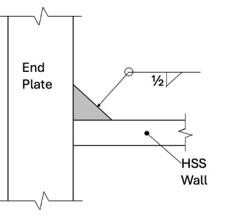
With an axial tension load on the HSS member, the load action is oriented at θ = 90° to the weld axis and kds = 1.5. Substituting properties into Eq. (3), the required weld effective throat is:

This well exceeds the minimum fillet weld size in Table J2.4 of the AISC Specification. Base metal shear, governed by Section J4 and mentioned in Table J2.5 of the AISC Specification, will be non-critical due to the end-plate thickness. From the AISC Manual Table 8-12, this weld will likely require 4 weld passes. The detail in Figure 7 results.
With a Fillet-Reinforced PJP Weld
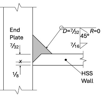
From the foregoing discussion and Figure 5, a root face landing of f = 1/8 in. and a groove angle of 45o are chosen, for which no effective throat deduction (or “Z loss”) is required. This gives a preparation depth of 0.224 in. or 7/32 in.
For a fillet-reinforced PJP weld to develop the attached HSS wall yield resistance, over a unit length of weld or wall (e.g. 1 in.), one can equate the available strength of the weld to the yield resistance of the attached HSS. Since the resistance of the weld metal is less than the resistance of the base metal in shear rupture:
φRn = φweldFnwAwe = φHSSFy-HSSAHSS (4)
where φHSS = 0.9 and φweld = 0.80 and Fnw = 0.60FEXX (AISC Specification Table J2.5), with FEXX being the ultimate strength of the weld metal. Thus, Eq. (4) can be simplified to:
0.80(0.60)FEXXS(1in.) = 0.9Fy-HSSt(1in.) (5)
Hence,

where S is the required weld effective throat thickness for a HSS wall thickness of t. Substituting properties into Eq. (6), the required weld effective throat is:

For the weld geometry in Figure 8, if the fillet leg length on both the end plate and the HSS is 7/16 in., the resulting weld effective throat (the diagonal length from the root that is perpendicular to the diagrammatic weld face) can be calculated as S = 0.468 in., which is sufficient. This fillet size is almost the same as the design for a fillet weld only (without the PJP groove weld), making the fillet-reinforced PJP option unattractive. AISC Manual Table 8-12 indicates that this joint likely requires 5 weld passes. This outcome is due to the considerable benefit of the fillet weld strength-enhancement factor (of 1.5 in this application), for a fillet weld to a round HSS, which disappears in the fillet-reinforced PJP weld calculation. Note, however, that if the HSS member had been rectangular (or square) in this tension connection, the fillet weld strength-enhancement factor would have been disallowed in the fillet-weld-only case and the weld (leg) size – for the same HSS wall thickness – would have been ¾ in., yet the same detail in Figure 8 would still apply.
References
AISC. 2022. “Specification for Structural Steel Buildings”, ANSI/AISC 360–22, American Institute of Steel Construction, Chicago, IL.
AISC. 2023. “Steel Construction Manual”, 16th edition, American Institute of Steel Construction, Chicago, IL.
AWS. 2020. “Structural Welding Code – Steel”, AWS D1.1/D1.1M:2020, 24th edition, American Welding Society, Miami, FL.
Miller, D.K. 2017. “Welded Connections – A Primer for Engineers”, Steel Design Guide No. 21, 2nd edition, American Institute of Steel Construction, Chicago, IL.
Packer, J.A. and Olson, K. 2024. “Hollow Structural Section Connections”, Steel Design Guide No. 24, 2nd edition, American Institute of Steel Construction, Chicago, IL.