FE-Based Design of HSS Connections
By Jeffrey A. Packer
Bahen/Tanenbaum Professor of Civil Engineering, University of Toronto, Ontario, Canada
FE Analysis for Research
Finite element (FE) analysis has been used as a tool for research on structural steel connections since the 1970s. As the speed of computers and the size of problems they can handle has grown exponentially with time, software has similarly advanced, leading to the immense popularity of FE methods in research. Owing to limitations in computational facilities in the 1990s, shell elements were the most widely employed to model tubular connections. Now, with an immense increase in computational power, there is a trend toward nonlinear analysis of FE models meshed with solid elements. The two most popular commercial FE programs are ANSYS and ABAQUS, and two different solution techniques are available: implicit and explicit solvers. State-of-the-art reviews of FE application to welded and bolted HSS connections are even performed periodically (e.g., van der Vegte et al., 2010).
Apart from some analytical or closed-form solutions (e.g., yield line theory), very early research on HSS connections was dominated by physical testing of laboratory specimens, leading to empirical rules based on “experimental tests.” Due to the high cost and time-consuming nature of experimental work, current research tends to involve a much smaller set of laboratory experiments with FE models validated against these experiments, followed by a large parametric study generating “numerical tests.” In this way, a very large database can be developed from which design rules can be proposed. These are still empirical and subject to the range of validity of the database. The ability of modern FE models to replicate the behavior of laboratory connection tests is illustrated in Figure 1. Besides qualitative pictorial agreement of the failure mode and deformations, the numerically simulated and experimental branch load versus displacement relationships need to be quantitatively matched.
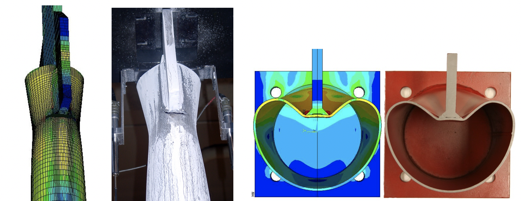
(2 Images Right) (a) a slotted HSS end connection loaded in tension, failing by circumferential fracture;
(2 Images Left) (b) a longitudinal plate connection under branch axial compression, failing by chord plastification [section view] (University of Toronto).
FE Analysis for Design
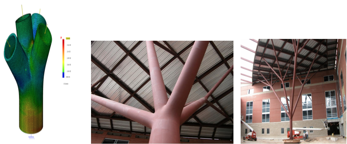
The AISC 360 Specification (AISC, 2016) Chapters J and K offer a set of pertinent limit states to be considered in the design of an HSS connection. Some specific connection arrangements have resistance formulas associated with particular limit states, but these are often constrained by limits of applicability. AISC Design Guide No. 24 (Packer et al., 2010) expands on the static design of HSS connections considerably but still deals only with planar, simple connection cases. There is a large number of HSS connection geometries and loading conditions that are not covered by the AISC Specification or Design Guide No. 24, such as shown in Figures 2 and 3, and for such cases, design using FE analysis is an option and is permitted by AISC 360-16 Appendix 1. The Commentary to Appendix 1 specifically cites nonlinear FE analysis as a design method; however, only engineers experienced in the use of FE analysis should attempt this. Both welded and bolted connections can be designed by FE methods with elastic analysis (sufficient for fatigue design) or inelastic analysis (generally used to capture the ultimate limit state). Any limitations of the chosen software should always be checked to ensure that the software has the capability of properly investigating and capturing the limit state being investigated. This may involve confirmation of nonlinear analysis, failure criteria, sufficient number of nodes/elements permitted, element types in the library, etc.

Aspects of FE Modeling
Features to be considered are now even described in some steel design codes, such as EN 1993-1-14 (CEN, 2020). The eventual FE model is, ideally, validated against one or more laboratory experiments on identical connections, but this is commonly not possible in design situations. In this case, the FE modeling technique and chosen mesh/material parameters should be verified against some FE analyses from the research literature or from collected benchmark cases (which in turn have been validated), such as by Wald et al. (2017). The following describes aspects that need to be considered in order to perform FE modeling of hollow structural section connections.
Element Type and Meshing
Plate and shell elements are usually chosen to mesh a structure when one of its dimensions is much smaller than the other two dimensions (e.g., for small thicknesses). HSS members are usually relatively stocky and computing power now enables the more universal solid or 3D “brick” elements for a wide variety of connections. Solid elements usually have three translational DOFs at each node. Elements with full or reduced integration are options. Eight-noded solid elements (rather than 20-noded solid elements) have been found to be ideal to model hollow sections for a wide variety of connection cases. Thus, library elements SOLID45 or SOLID185 in ANSYS or C3D8R in ABAQUS are popular (Martinez Saucedo et al., 2006; Voth and Packer, 2012; Tousignant and Packer, 2017; Kuhn et al., 2019; Kožich et al., 2019; Bu and Packer, 2020). Solid or prism volume elements will be necessary for modeling welds and bolts. For bolts, one needs to obtain the correct bolt stiffness and ultimate strength so these can be modeled in three parts: (i) the head, (ii) a cylinder corresponding to the shank diameter and length, and (iii) a cylinder corresponding to the thread diameter and length. The nominal dimensions of the HSS members should be used but in conjunction with the “design wall thickness.”
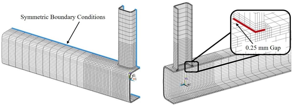
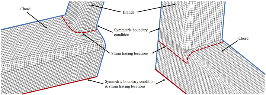
A relatively fine mesh is needed around points of load application and force transfer, as well as points of stress concentration, but the mesh may become coarser away from such critical regions to reduce the overall model size (see Figure 4). Care must be taken with the shape of elements to ensure that the element aspect ratio does not influence the accuracy of the solution. The rounded corners of square and rectangular HSS usually need to be modeled (Figure 4). For cold-formed HSS, the inside corner radius can be taken as the HSS wall thickness and the outside corner radius as twice the wall thickness. Instead of modeling the entire connection, one can sometimes take advantage of planes of symmetry and just model ½, ¼ or ⅛ of the entire connection (Figure 4). Multiple layers of elements are usually required through the thickness of HSS members (Figures 3 and 4). If an HSS wall is prone to buckling under compression loading, it is prudent to give the wall an initial imperfection in the direction of buckling; a deformed shape described by a sinusoidal function, with a mid-height bulge of 1% of the wall height, is typical. Overall mesh discretization is finally confirmed by means of a convergence study (see below).
The size or type of weld may be influential in some connections, for example for fatigue analysis, or for ultimate limit states involving fillet welds. Fillet welds enlarge the branch footprint, and it may be important to transfer load only though the weld (Figures 3 and 4), which can be achieved by leaving a small gap between the HSS members (Figure 4). CJP and PJP welds can be modeled by joining HSS-to-HSS nodes along the groove depth, while fillet welds can be modeled with solid elements joined to the respective HSS members.
All of the foregoing modeling parameters need to be varied in a so-called sensitivity study to conclude with an FE model, which is not excessively large (computationally) but provides convergence. This term implies that only very small changes in the ultimate load and load-deformation behavior occur with additional refinement of the FE model.
Material Properties
Material properties, such as yield stress (fy) and Young’s Modulus (E), should be taken as the nominal values from the AISC Specification since the analysis is being used for design. A quad-linear engineering stress-strain “curve,” such as shown in Figure 5(a), is a recommended option for cold-formed steel (CEN, 2020). This neglects necking and fracture, but the ultimate limit state for design purposes can be deemed to occur within this strain range. For input to the FE program, the engineering stress-strain (f-ε) curve of Figure 5(a) needs to be converted to true stress-strain as shown in Figure 5(b),according to (Boresi and Schmidt, 2003):
True stress = ftrue = f(l+ε)
Equation 1
True strain = εtrue = ln(l+ε)
Equation 2
For analysis of the ultimate limit state, the FE program used should have both nonlinear material and geometric analysis capability with these features activated. Analysis for fatigue design can be performed with linear-elastic material properties. Material properties for the welds can be taken to be the same as for the base metal.
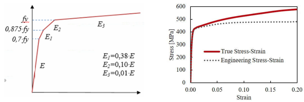
Image Left: (a) Engineering stress-strain curve | Image Right (b) True stress strain curve
Boundary Conditions and Loading
The boundary conditions of an FE model should be treated in a way that ensures a realistic or conservative model of the real structure. The chosen support conditions should have the same effect and provide the same stiffness to the numerical model as the physical supports have on the real structure. When plate, shell or solid elements are located at the boundary of an FE model, concentrated or “point” boundary conditions should be avoided so that numerical stress concentrations do not occur. Symmetric boundary conditions can be modeled at planes of symmetry but should only be used where the expected structural behavior (failure modes, buckling modes, deformed shapes, etc.) has been verified to be symmetrical. For monotonic loading, FE models are typically loaded under displacement control by applying incremental static displacements to the end of one member (e.g., an HSS branch). Load control may be used for linear analysis. Typically, it is necessary to run many combinations of factored loads in a practical design exercise.
Ultimate Load Criteria
The ultimate capacity should be determined from the connection load-deformation response by taking the “ultimate load” from the following two criteria illustrated in Figure 6 (CEN, 2020):
C1: The peak load if this occurs at a deformation/strain before a deformation or strain limit is reached.
C2: The load corresponding to a limiting deformation or strain if this occurs on the load-deformation path prior to a peak load being achieved.
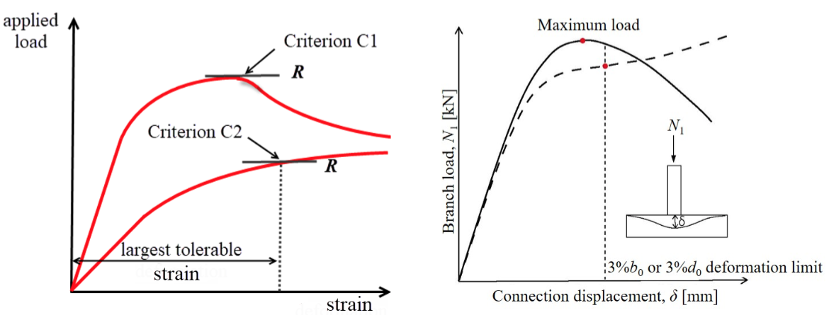
Image Left: (a) strain-based limit | Image right (b) deformation-based limit
An ultimate deformation limit corresponding to a chord-face deformation (an indentation inwards or outwards) of 3% of the HSS chord width or diameter (i.e., 0.03B or 0.03D), shown in Figure 6(b), was proposed initially by Lu et al. (1994) for flexible HSS connections. The utility of this “3% deformation limit” was confirmed by other researchers, hence why this criterion was adopted by the International Institute of Welding (IIW) in the 1990s and then by CIDECT. While this works well for deformable connections, under branch compression or tension loading, stiff connections may be prone to rupture at low deformations prior to a pronounced peak load being achieved. This then requires the introduction of a fracture criterion into the FE program, which ideally needs to be strain-based.
One way in which FE analysts have accommodated fracture in research is to set a maximum equivalent strain at which an element “death feature” is activated. When the critical strain is reached, the stiffness and the stress of that element are reduced to near zero and the inactive element thereafter sheds load to the surrounding elements. This is physically comparable to the initiation and propagation of a crack through the material. Unfortunately, the critical maximum equivalent strain varies widely according to the connection type, degree of constraint, loading and even mesh discretization (Martinez Saucedo et al., 2006; Voth and Packer, 2012; Tousignant and Packer, 2017) and is often set pragmatically by calibration to laboratory experiments. This is not possible when FE analysis is used for design, so an alternate approach is to set a maximum inelastic strain (Figure 6(a)) along the load-strain curve for every element. EN 1993-1-14 (CEN, 2020) refers to Annex C (informative) of EN 1993-1-5 (CEN, 2006) where a limiting principal strain of 5% is recommended for design by FE analysis. However, the location of strain measurement for this limit state is critical. In FE models, extreme strain occurs in buckles as well as in regions where geometry change occurs, such as at a weld toe. Hence, in welded connections, the maximum principal strain of 5% needs to be measured at a minimum clear standoff distance from geometry change regions and a distance from a weld toe of 0.5t is recommended (Kožich et al., 2019; Bu and Packer, 2020), where t is the thickness of the HSS member at the weld toe. Although the maximum principal strain needs to be checked at all elements, the strain history can often be monitored and recorded just at obvious critical locations once these are known (e.g., Figure 7).
Once the “ultimate” or nominal strength of a connection has been determined per the above procedures, one needs to obtain an available design strength by applying an appropriate resistance factor (for LRFD) or safety factor (for ASD). Depending on the nature of the failure mode, as being either ductile or brittle, one can be guided by the resistance/safety factors for typical limit states in Chapters J and K of the AISC Specification (AISC, 2016). Resistance factors range from 0.75 for tensile rupture (e.g., Section J4.1(b)) to 1.00 for shear yielding (e.g., Section J4.2(a)) or local yielding/plastification (e.g., Section J10.2).
References
AISC. 2016. “Specification for Structural Steel Buildings”, ANSI/AISC 360-16, American Institute of Steel Construction, Chicago, IL.
Boresi, A.P. and Schmidt, R.J. 2003. “Advanced Mechanics of Materials”, 6th edition, Wiley, Hoboken, NJ.
Bu, X.D. and Packer, J.A. 2020. “Chord End Distance Effect on RHS Connections”, Journal of Constructional Steel Research, Vol. 168, 150592.
CEN. 2006. “Eurocode 3: Design of Steel Structures – Part 1-5: Plated Structural Elements”, EN 1993-1-5, European Committee for Standardization, Brussels, Belgium.
CEN. 2020. “Eurocode 3: Design of Steel Structures – Part 1-14: Design Assisted by Finite Element Analysis”, EN 1993-1-14, European Committee for Standardization, Brussels, Belgium.
Kožich, M., Jehlička, P., Wald, F., Bu, X.D., Packer, J.A. and Kabeláč, J. 2019. “Towards Establishing a Design Resistance for Hollow Section Joints”, Proceedings of the 17th International Symposium on Tubular Structures, Singapore, pp. 643-650.
Kuhn. J., Packer, J.A. and Fan, Y. 2019. “Rectangular Hollow Section Webs under Transverse Compression”, Canadian Journal of Civil Engineering, Vol. 46, pp. 810-827.
Lu, L.H., de Winkel, G.D., Yu, Y. and Wardenier, J. 1994. “Deformation Limit for the Ultimate Strength of Hollow Section Joints”, Proceedings of the 6th International Symposium on Tubular Structures, Melbourne, Australia, pp. 341-348.
Martinez Saucedo, G., Packer, J.A. and Willibald, S. 2006. “Parametric Finite Element Study of Slotted End Connections to Circular Hollow Sections”, Engineering Structures, Vol. 28, No. 14, pp. 1956-1971.
Packer, J.A., Sherman, D. and Lecce, M. 2010. “Hollow Structural Section Connections”, Steel Design Guide No. 24, 1st edition, American Institute of Steel Construction, Chicago, IL.
Tousignant, K. and Packer, J.A. 2017. “Numerical Investigation of Fillet Welds in HSS-to-Rigid End-Plate Connections”, ASCE Journal of Structural Engineering, Vol. 143, No. 12, 04017165:1-16.
van der Vegte, G.J., Wardenier, J. and Puthli, R.S. 2010. “FE Analysis for Welded Hollow-Section Joints and Bolted Joints”, ICE Structures and Buildings, Vol. 163, Issue SB6, pp. 427-437.
April 2020