Considerations for Use of HSS in Seismic Frame Systems
By Jason McCormick
Associate Professor, Civil & Environmental Engineering, University of Michigan, Ann Arbor, MI, USA
Hollow structural sections (HSS) have many favorable properties such as good compression, bending, and torsional resistance; a high strength-to-weight ratio; and smooth lines that work well for architecturally exposed steel. As a result, HSS have been employed in a variety of structural applications under largely static loads, including as chords and braces in truss systems, as supports in cladding systems, and as columns in building frames. The advantages of HSS members also can translate to seismic frame systems where the torsional resistance can limit the need for lateral bracing used to prevent lateral-torsional and flexural-torsional buckling in beams and columns, the high strength-to-weight ratio can help limit the seismic mass of the structure thereby reducing expected loads, and their architectural appeal provides more flexibility in the configuration of the system. However, HSS used in seismic systems need to meet specific material and member requirements in order to ensure that the seismic force-resisting system behaves in a ductile manner under significant inelastic deformations.
Current seismic design philosophy for steel systems (AISC 2016a) recognizes that it is often impractical from an economic standpoint to ensure that a structure remains elastic under a rare seismic event (Hamburger and Malley 2016; Sabelli et al. 2013). Rather, seismic frames are designed so as not to collapse under these events thereby ensuring occupant safety, but allowing significant inelastic deformation in the structural system and damage to non-structural components (ASCE 2016). This philosophy has led to a capacity-based approach for the most ductile seismic steel systems where specific elements are intended to act as fuses and undergo controlled inelastic behavior out to specified deformation levels. The majority of requirements for members in seismic systems are to ensure that these inelastic deformation levels can be achieved without collapse or sudden failure of the structure.
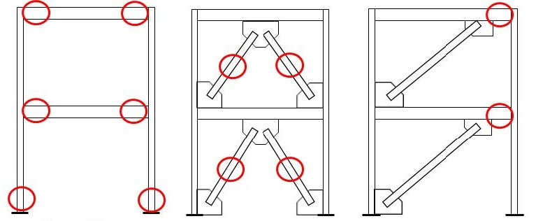
The expected level of inelastic deformation and required ductility are used to classify a steel seismic frame into either an ordinary, intermediate, or special system with each subsequently requiring more restrictive detailing as the required design strength of the system decreases in order to take advantage of the system’s ductility (ASCE 2016). The AISC Seismic Provisions (AISC 341-16) specify the detailing requirements in order to meet the intent of each of these systems (AISC 2016a). Moment frames or composite moment frames can be designed as ordinary, intermediate or special moment frames, while concentrically braced frames and composite concentrically braced frames can be designed as ordinary or special braced frames. Eccentrically braced frames and composite eccentrically braced frames only have a single level of design that is similar to that of a special system. For these systems (Figure 1), the limitations for their use as ordinary, intermediate and special systems are provided in ASCE 7-16 Table 12.2-1 along with the appropriate parameters for calculating the anticipated earthquake loads (ASCE 2016).

Left Image (a) Moment Frame and Composite Moment Frame
Middle Image (b) Concentrically Braced Frame and Composite Concentrically Braced Frame
Right Image (c) Eccentrically Braced Frame and Composite Eccentrically Braced Frame
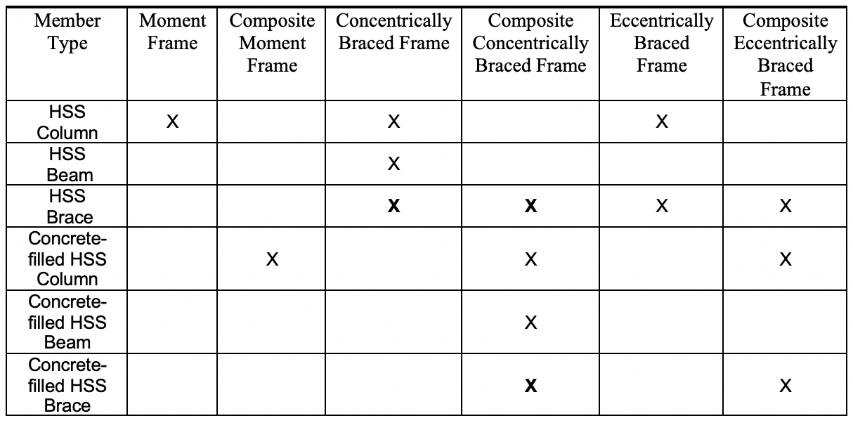
Relevant seismic systems that can utilize HSS are steel moment-resisting frames, composite moment-resisting frames, steel concentrically braced frames, composite concentrically braced frames, steel eccentrically braced frames and composite eccentrically braced frames. For steel special moment frames, the beam ends and the bases of the first story columns act as the fuses through the formation of plastic hinges to ensure that the inelastic behavior is distributed over the height of the building. For steel special concentrically braced frames, the braces or fuses are expected to undergo tension yielding and compression buckling over the height of the braced frame system. For steel eccentrically braced frames, the link section within the beam acts as the fuse and is expected to undergo shear yielding to accommodate the expected inelastic behavior. Through a capacity-based design, the rest of the system is designed to ensure that the expected forces and moments developed by these fuses can be sustained without significant inelastic deformation in other members or connections. Given the current AISC Seismic Provisions (AISC 341-16) and AISC Prequalified Connections for Special and Intermediate Moment Frames for Seismic Applications (AISC 358-16), the opportunities for use of HSS in seismic frame systems are provided in Table 1 with those cases where the HSS also acts as the fuse in these systems shown in bold. For the composite systems, the HSS member is assumed to be concrete-filled and the desired mechanism for the frame remains the same as mentioned above.

Material requirements for the use of HSS in seismic design are largely dictated by the material’s ability to undergo inelastic behavior without brittle failure and to meet weldability needs. As a result, there are restrictions on the steel material specification for HSS used in a seismic force resisting system. For the seismic frames shown in Figure 1, square, rectangular, and circular HSS are limited to ASTM A500 Grade B, ASTM A500 Grade C, ASTM A501 and ASTM A1085 designated steel. Pipe sections with an ASTM A53 designation also are allowed. Most ASTM A500 HSS are produced as dual certified Grade B and C, so it is more beneficial to specify ASTM A500 Grade C versus ASTM A500 Grade B in order to take advantage of the higher yield strength (46 ksi versus 42 ksi for circular sections and 50 ksi versus 46 ksi for square and rectangular sections). However, ASTM A1085 steel is the most desirable for seismic applications because of its tighter mass tolerances, maximum specified yield strength (50 ksi for circular, square, and rectangular sections), minimum Charpy V-notch requirements, and reduced variability in yield and tensile strength compared to the specified minimum values. The stricter requirements for ASTM A1085 also have the benefit of allowing the full wall thickness of the HSS to be used when calculating the strength of the member as opposed to HSS designated as ASTM A500 Grade B or C where a reduction of the wall thickness must be taken to account for manufactures producing HSS on the lower end of the dimensional tolerances with no specified mass tolerance (Packer and Henderson 1997).
The capacity-based design approach also requires that the forces and moments in the non-fuse elements that are intended to remain elastic or undergo minimal inelastic deformation be calculated accurately to ensure that the desired mechanism develops. As a result, the required strength for these elements is calculated based on the expected strength (AISC 341-16) of the member acting as a fuse. With respect to HSS, this means that the expected strength of HSS columns or concrete-filled HSS columns in seismic moment frames needs to be considered when determining the required strength of the column base and the expected strength of an HSS or concrete-filled HSS brace in a concentrically braced frame needs to be considered when determining the required strength of the beams, columns and connections in the braced frame. In order to calculate the expected strength, the following equations can be used to obtain the
expected yield, fy,,exp, and tensile, fu,,exp, strength:
fy,exp = Ryfy
fu,exp = Rtfu
where Ry is the ratio of the expected yield stress to the specified minimum yield stress, fy, and Rt is the ratio of expected tensile strength to the specified minimum tensile strength, fu. The values for Ry and Rt are provided in Table 2 for ASTM material designations applicable to HSS. The smaller Ry and Rt values for ASTM A1085 result from the tighter dimensional and mass tolerances to meet this designation. These smaller values are beneficial from a design standpoint in that the required strengths that the rest of the members and connections within the frame need to be designed for also will be lower.
| ASTM Designation | Ry | Rt |
| ASTM A500/A500M Gr. B | 1.4 | 1.3 |
| ASTM A500/A500M Gr. C | 1.3 | 1.2 |
| ASTM A501/A501M | 1.4 | 1.3 |
| ASTM A53/A53M | 1.6 | 1.2 |
| ASTM A1085/A1085M | 1.25 | 1.15 |
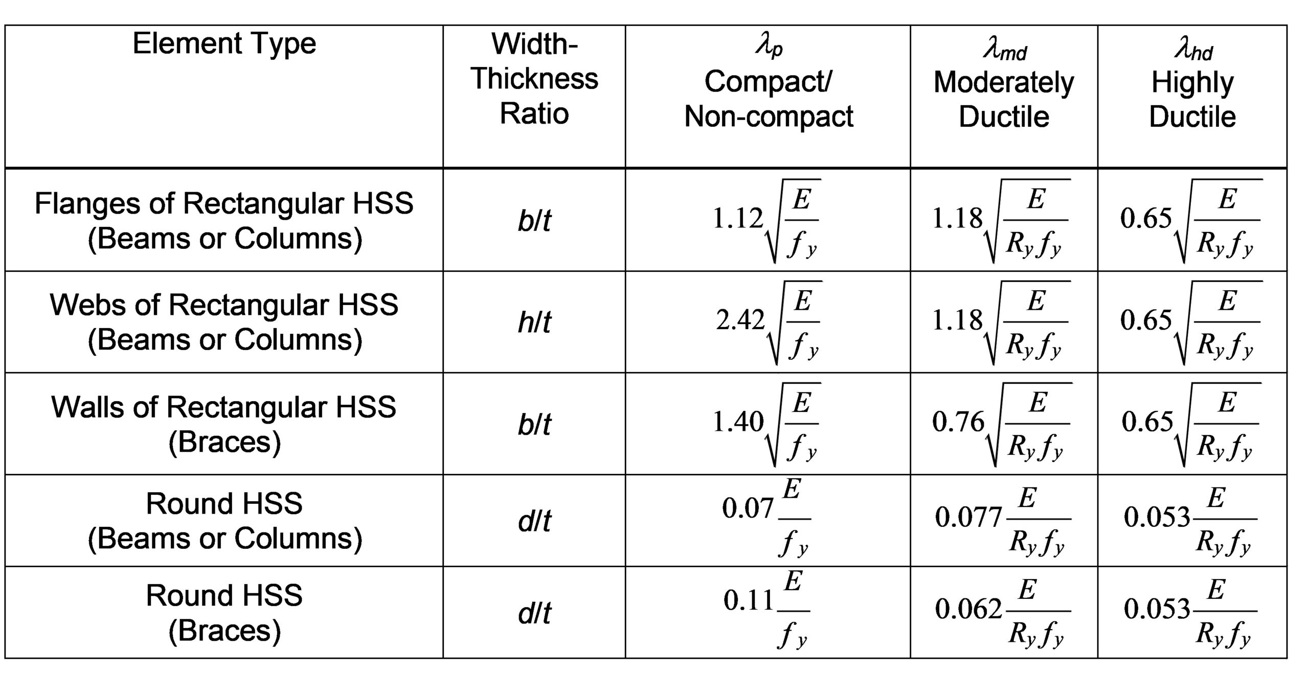
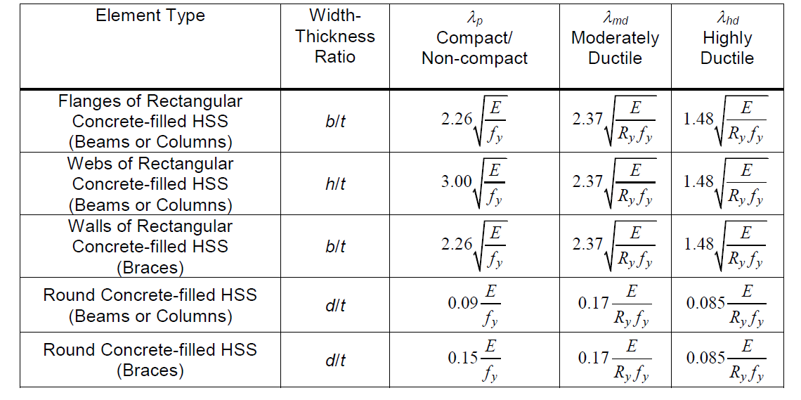
Since seismic force-resisting systems are expected to undergo significant inelastic rotations, particularly when designed as special systems, the members of seismic frames need to have adequate ductility and capacity to ensure the desired behavior or mechanism is achieved, even those members that do not act as fuses and are intended to remain elastic. In order to achieve this behavior, local buckling, which can lead to significant degradation of the moment capacity of HSS and early onset of fracture at the corners of square and rectangular HSS due to cycling needs to be avoided. For this reason, the AISC Seismic Provisions(AISC 341-16), impose width-thickness limits for steel elements of HSS in compression for different levels of expected inelastic rotation (AISC 2016a). For concrete-filled HSS, these limits are applied to the outer steel tube, but account for the beneficial nature of the concrete-infill in inhibiting local buckling. For seismic force-resisting systems that utilize HSS members that are not expected to see significant inelastic behavior and are designed for larger design loads, such as ordinary systems, local slenderness ratios that ensure the HSS member is compact are typically adequate. These width-thickness ratios are given in the AISC Specification for Structural Steel Buildings (AISC 360-16) as λp which ensures that the plastic capacity of the cross-section can be developed prior to local buckling assuming moderate ductility demands (AISC 2016b). As inelastic demands are expected to increase with intermediate and special seismic systems, further restrictions are placed on the local slenderness of HSS so as to avoid local buckling that can lead to limited capacity and rapid degradation of capacity under larger inelastic cycling. The AISC Seismic Provisions thus set moderately ductile, λmd, and highly ductile, λhd, width-thickness limits (AISC 2016a). As with the compact section limits specified in AISC 360-16, the moderately ductile limits are meant to achieve similar behavior, but account for the influence of cyclic loading associated with an earthquake often resulting in more stringent requirements (Hamburger and Malley 2016). The local slenderness limits for HSS and concrete-filled HSS are provided in Table 3 and 4, respectively.


In evaluating these local slenderness limits, the benefits of the concrete in-fill are clear in regards to its ability to inhibit local buckling. The limiting local slenderness ratios shown in Table 4 for concrete-filled HSS all exceed those specified for unfilled HSS. The further benefits of using ASTM A1085 steel for HSS as opposed to ASTM A500 steel also becomes apparent in that a larger thickness value can be used in calculating the local slenderness ratio for an HSS element resulting in a smaller ratio than that calculated for ASTM A500 steel. Likewise, the smaller Ry value associated with ASTM A1085 steel also leads to larger local slenderness limits.
The local slenderness requirements for specific members within a seismic steel frame are dependent on the type of system, classification of the systems (ordinary, intermediate, and special), and whether the member is expected to undergo significant inelastic behavior (i.e. act as a fuse). Table 5 provides the local slenderness requirements for the different members within the different seismic frame systems. As the expected level of inelasticity increases for a given member and frame, the limiting local slenderness ratio decreases to ensure that local buckling will not decrease the capacity and ductility of the member.
| System | Beam | Column | Brace | Link |
| OMF | λp | λp | — | — |
| C-OMF | λp | λp | — | — |
| IMF | λmd | λmd | — | — |
| C-IMF | λmd | λmd | — | — |
| SMF | λhd | λhd | — | — |
| C-SMF | λhd | λhd | — | — |
| OCBF | λp | λp | λmd | — |
| C-OBF | λp | λp | λp | — |
| SCBF | λhd | λhd | λhd | — |
| C-SCBF | λmd | λhd | λhd | — |
| EBF | λmd | λhd | λmd | λhd |
Note: “O”, “I”, and “S” refer to ordinary, intermediate, and special. “MF” refers to moment frame. “BF” refers to braced frame (concentric or eccentric). “C-” refers to a composite frame.
A few further points should be noted in regards to the use of HSS in seismic design. For intermediate and special moment frame systems, there are currently no prequalified connections for HSS beams to HSS columns and the only prequalified connections that allow for the use of HSS or concrete-filled HSS are proprietary. Further, the limitations for which a connection is prequalified may dictate the allowable sizes of an HSS member. For braces in special concentrically braced frame systems, the advantages of using an HSS can be offset by the need to design the rest of the frame components based on the expected strength of the brace (Sabelli et al. 2013). The large Ry values associated with HSS increases the forces for which the other components need to be designed. Designating ASTM A1085 is one means of reducing this effect. It should also be noted that square and rectangular HSS braces tend to facture at smaller drifts than circular or wide flange braces due to a concentration of strain in the corners of the tubes once a plastic hinge forms in the brace. Designers should be aware of this fact when using HSS braces.
The advantages of HSS can provide benefits to seismic frame systems, particularly in situations where bidirectional loading can be expected. The discussion above focuses on some general requirements for the use of HSS in these seismic systems. More specific requirements for the different systems can be found in AISC 341-16 (AISC 2016a), AISC 358-16 (AISC 2016c), NEHRP Seismic Design Technical Brief No. 2 (Hamburger and Malley 2016) and No. 8 (Sabelli et al. 2013), and CIDECT Design Guide 9 for Structural Hollow Section Column Connections (Kurobane 2004).
References
AISC. (2016a). “Seismic Provisions for Structural Steel Buildings”, ANSI/AISC 341-16. American Institute of Steel Construction, Chicago, IL.
AISC. (2016b). “Specifications for Structural Steel Buildings”. ANSI/AISC 360-16. American Institute of Steel Construction, Chicago, IL.
AISC. (2016c). “Prequalified Connection for Special and Intermediate Steel Moment Frames for Seismic Applications”, ANSI/AISC 358-16. American Institute of Steel Construction, Chicago, IL.
ASCE (2016). “Minimum design loads and associated criteria for buildings and other structures”, ASCE/SEI 7-16. American Society of Civil Engineers, Reston, VA, USA.
Hamburger, R.O and Malley, J.O. (2016). “Seismic Design of Steel Special Moment Frames: A Guide for Practicing Engineers, Second Edition, GCR 16-917-41, NEHRP Seismic Design Technical Brief No. 2, produced by the Applied Technology Council and Consortium of Universities for Research in Earthquake Engineering for the National Institute of Standards and Technology, Gaithersburg, MD.
Kurobane, Y., Packer, J.A., Wardenier, J., and Yeomans, N. (2004). Design Guide 9: For Structural Hollow Section Column Sections. CIDECT, Germany.
Packer, J.A. and Henderson, J.E. (1997). “Hollow Structural Connections and Trusses – A Design Guide”. Canadian Institute of Steel Construction, Ontario, Canada.
Sabelli, R., Roeder, C.W., and Hajjar, J.F. (2013). “Seismic Design of Steel Special Concentrically Braced Frame Systems: A Guide for Practicing Engineers, GCR 13-917-24, NEHRP Seismic Design Technical Brief No. 8, produced by the NEHRP Consultants Joint Venture, a partnership of the Applied Technology Council and Consortium of Universities for Research in Earthquake Engineering, for the National Institute of Standards and Technology, Gaithersburg, MD.
July 2017