Composite Concrete Filled HSS: Design Considerations
By Jason Ericksen, SE
Technical Consultant to the Steel Tube Institute
Kim Olson and Benjamin Kaan authored an eNews article titled “Practical Guidance for Concrete Filled HSS Columns” in September 2015. The article discussed some of the benefits of filling HSS columns with concrete, including increased strength and a potential reduction in fire protection requirements. As the title implies, the article focused on the practical aspects of designing, fabricating, erecting, and filling the columns. Guidelines for concrete placement and overall constructability were included. A web seminar was presented by STI in July 2016 (“Composite Columns: Design and Practical Considerations”) that combined the guidelines from this article with a more detailed discussion of the design of composite concrete-filled HSS columns. This article includes information from the design aspects of that seminar, focusing on determining the nominal strength of beam-column members for round and rectangular filled HSS members without additional steel reinforcement.
Composite Design Using AISC 360-10
The design of composite members is covered in the AISC Specification in Chapter I. The 2010 Specification is used for this discussion and will be referred to as AISC 360-10. Before getting into the details of filled composite members, it is worth noting a few items that apply to all composite designs according to AISC 360-10.
Section I1.2 discusses how the nominal strength of the composite section is determined. It specifies three things; the nominal strength is determined using the plastic stress distribution method or the strain compatibility method, the tensile strength of concrete shall be neglected, and local buckling effects must be considered for filled composite members.
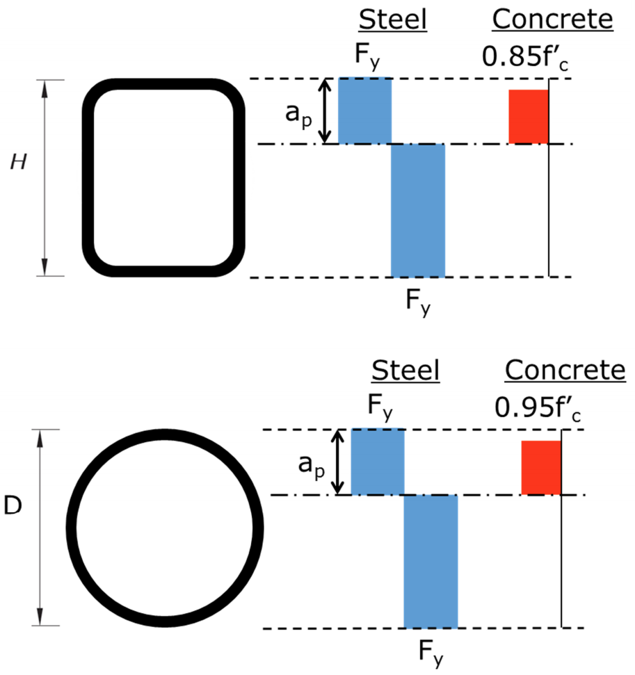
Section I1.2a contains a description of the plastic stress distribution method. The nominal strength is computed assuming the steel components have reached a stress of Fy in either tension or compression and the concrete stress is assumed to be 0.85f’c in compression. An increase to 0.95 f’c is allowed for round filled members to account for the effects of concrete confinement. It is relatively straight-forward to apply this method. However, it cannot be used in certain circumstances, mainly when members are classified as noncompact or slender for local buckling.
The strain compatibility method, covered in Section I1.2b, requires that a linear distribution of strains across the section is used along with a stress-strain relationship (for steel and concrete) that has been obtained from tests or published results. Additionally, it is required that the concrete compressive strain is limited to 0.003 in./in. This method is generally only used for noncompact and slender members.
The nominal strength of the composite member does not have to be taken as less than the nominal strength of the steel section itself. This is stated in Section I2.2b. It is not uncommon for the steel section to control the calculated axial strength for members with small b/t ratios and where the steel section is a larger portion of the total composite area. The strength of HSS steel sections (without composite action) is not covered in this discussion.
Recommendations
The following suggestions and observations about the design of filled composite HSS members will be made before the details of determining the nominal strength of the members is discussed.
1. Limit HSS member selection to those that are compact: The complexity of the design for noncompact and slender members is much greater than that for compact members. Most available HSS sections are compact for both compression and flexure for composite design. (Note that one major benefit of filling an HSS with concrete is that the b/t limits are increased, resulting in fewer members that are not compact.)
2. Use concrete strength of 4 or 5 ksi: Filling an HSS member with concrete increases the strength of the member, but the additional gains for higher-strength concrete are limited. As stated earlier, a major benefit to the nominal strength is increasing the b/t limits, allowing the full yield strength of the steel to be utilized for members with higher width-thickness ratios in the walls (i.e. more sections can use the plastic stress distribution method). The effect of concrete strength is more pronounced in larger sections (HSS 12 and larger) and members with thinner walls. Also, as stated earlier, the steel section strength may control for members with relatively thick walls (low b/t ratios), meaning that the concrete material strength has no effect. The steel section strength may control mainly due to a smaller resistance factor for LRFD and a larger factor of safety for ASD for the composite members.
3. Reference the discussion by Louis F. Geschwindner in Engineering Journal – Second Quarter 2010: The discussion covers the original paper by Roberto T. Leon and Jerome F. Hajjar “Limit State Response of Composite Columns and Beam-Columns” from Engineering Journal First Quarter, 2008. The discussion includes tables with equations for applying the plastic stress distribution method to rectangular and round filled HSS beam-columns. There are equations for calculating the flexural strength for compact sections and additional equations that allow a P-M curve to be created to evaluate beam-columns.
4. Use AISC 360-10 Commentary Fig. C-I3.7 equations: If noncompact or slender rectangular HSS sections are used, the figure includes the means to calculate the flexural strength for box sections. The equations can be used to evaluate the yield moment, My, for noncompact members and the first yield moment, Mcr, for slender members. These parameters are required to determine the nominal flexural strength of sections with noncompact or slender flanges or webs. The equations apply specifically to rectangular box sections, but can be applied to rectangular HSS sections with some comfort. The results of these equations were compared to a more accurate analysis using numerical methods. It was found that the commentary equations result in nominal flexural strengths within 5% (generally higher) of the numerical method for the noncompact and slender section surveyed by the author.
5. Use the plastic distribution method for beam-columns: There are two options for evaluating combined axial force and flexure for compact sections. One method is to use the equations of Section H1.1. The other is to use the plastic stress distribution method to build a P-M interaction curve. More effort is required to create the interaction curve, but significant additional capacity can be gained, especially for beam-columns with significant moments.
Material Limitations – I1.3
The concrete compressive strength, f’c, is limited as indicated below for the determination of nominal strengths. A higher strength concrete can be used for the stiffness calculations. The specified minimum yield strength of structural steel, Fy, shall not exceed 75 ksi.
Normal weight: 3 ksi ≤ f’c ≤ 10 ksi
Lightweight: 3 ksi ≤ f’c ≤ 6 ksi
Classification for Local Buckling – I1.4
Composite filled HSS sections are classified for local buckling as compact, noncompact, or slender for both axial compression and flexure. The limiting width-to-thickness ratios are indicated in Table I1.1A for axial and Table I1.1 for flexure. In addition to the familiar classifications, there is also a maximum permitted b/t ratio for each element. The maximum permitted ratios for webs of rectangular HSS and walls of round members in flexure are the same as the slender ratios. This indicates that slender round sections or HSS section with slender webs are not permitted. The limits for composite members are higher than the corresponding limits for the steel section alone because the concrete provides restraint to the local buckling of the HSS walls.
Nominal Axial Strength – I2.2
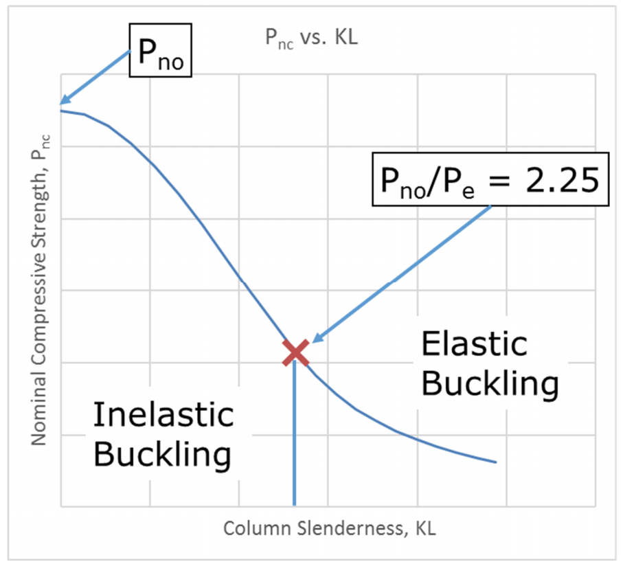
The area of the steel cross section must be at least 1% of the total composite cross section. All standard, domestically produced HSS sections meet this limitation. The column equations for encased composite equations from Section I2.2b are modified by Section I2.2b and used for filled composite members. Section I2.2b modifies the parameter Pno used in those equations. The column equations are similar to those used for steel sections (in Section E3), except that axial strengths (Pno and Pe) replace the stresses (Fy, Fe, and Fcr) used in those equations.
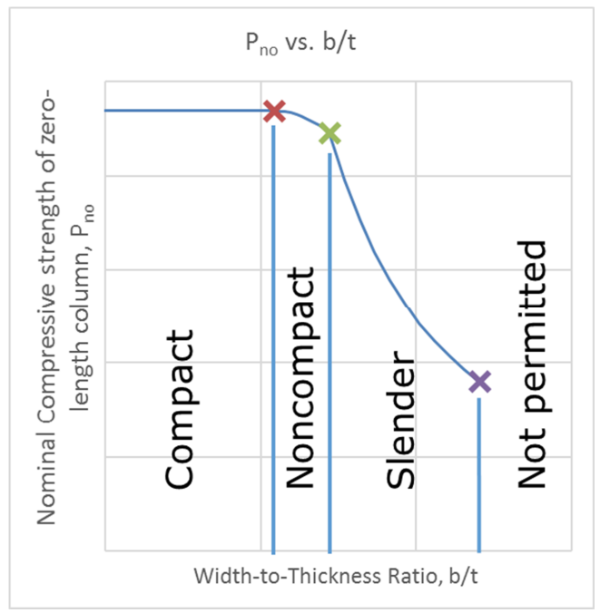
Two parameters are required to be calculated, Pno and Pe. Pe is the elastic critical buckling load and is determined from the effective stiffness of the composite section. Pno is determined from parts (a) for compact sections, (b) for noncompact sections, or (c) for slender sections. The calculations for Pno and Pe are straight-forward, with the equations for noncompact and slender sections requiring a bit more calculation, but nothing too complicated. By examining equations I2-9b and I2-9e for compact and slender sections, respectively, the method used can be identified. The plastic stress distribution is clearly used for compact sections. For slender sections, the compressive steel stress is limited to a critical buckling stress, Fcr, and the concrete stress is limited to 0.7f’c. This is less obvious, but the strain compatibility method is at work. This becomes more evident when the requirements of Section I3.4b for slender sections are considered. The section describes a linear stress distribution with the same steel and concrete stress limits in place. Figure 1 indicates how the nominal axial strength of the composite member for a zero-length member varies with the width-to-thickness ratio, b/t. Figure 2 indicates the nominal axial compressive strength, incorporating the length effects.
Nominal Flexural Strength – I3.4
The calculations for noncompact and slender sections for axial strength are not too onerous. However, the calculations to determine the nominal flexural strength for noncompact or slender composite filled HSS sections can become computationally intensive (even though the principles involved are straightforward). Section I3.4b is deceptively short – it contains general requirements and leaves the application of the required principles through detailed equations and calculations to engineering judgement. The calculations required for compact sections are nearly as complicated as those required for noncompact and slender sections.
Compact Sections
Part (a) of I3.4 states that Mn is equal to Mp, the moment corresponding to the plastic stress distribution over the composite section. Unlike most sections of AISC 360-10, it is left to the engineer to determine equations (or other methods) of determining Mp. This is where the discussion written by Louis Geschwindner (discussed above) comes in handy. Table C, point B contains equations for calculating Mp for rectangular HSS shapes that account for the rounded corners. Table D, point B contains equations for calculating Mp for round HSS shapes. Figure 3 indicates the stresses over the depth of HSS sections for the plastic stress distribution method as descried in Section I1.2a.
Noncompact Sections
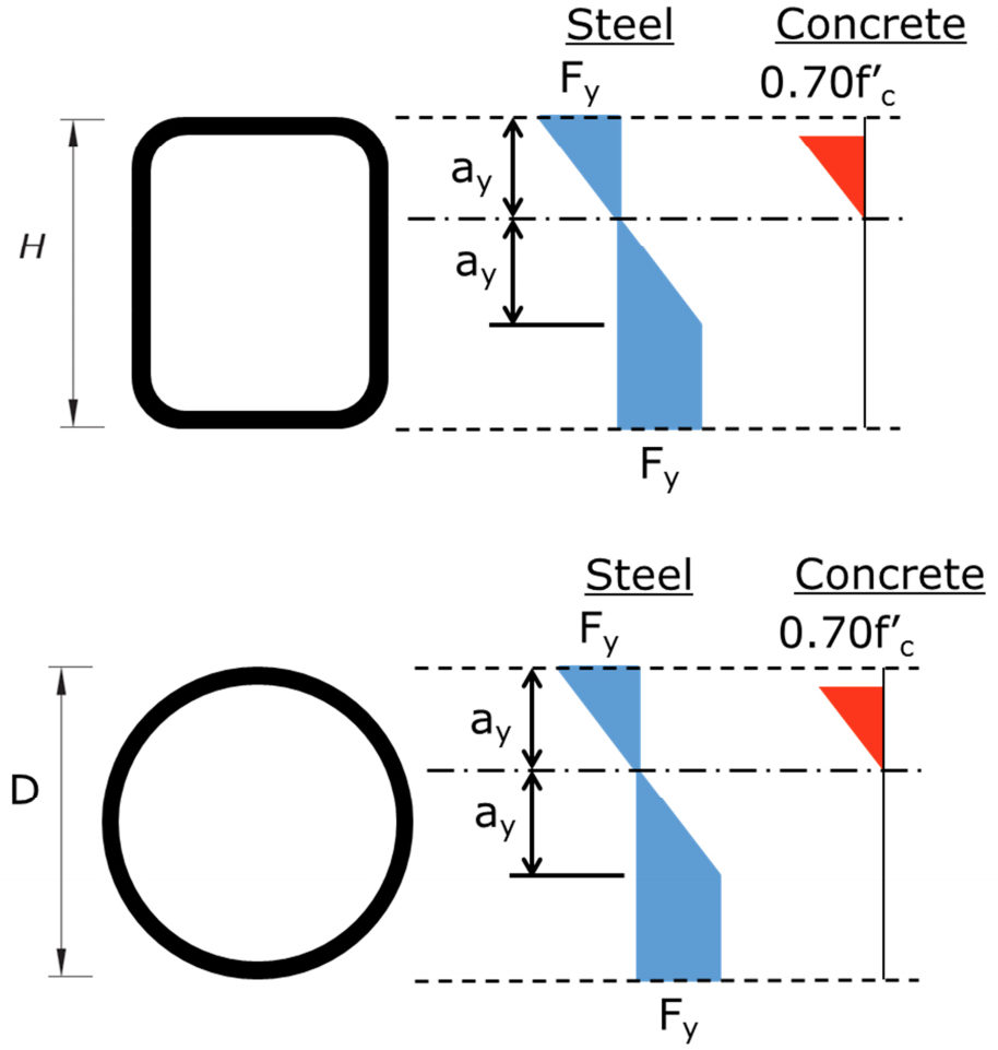
Part (b) gives equation I3-3a to determine Mn from Mp, My and the with-to-thickness ratio. The equation varies linearly from a value of Mp at a b/t equal to the compact/noncompact limit to My at the noncompact/slender limit. My is the yield moment corresponding to yield of the tension flange, first yield of the compression flange, and the concrete stress at maximum equal to 0.7f’c. A linear elastic stress distribution is assumed for concrete and elastic-plastic for steel. Figure 4 indicates the stresses assumed over the depth of the HSS sections.
Due to the fact that the stresses are varying over the height of the cross section and that the cross sections also vary with height (partial circles for round sections and rounded corners for rectangular sections), it is difficult to derive closed-form equations to calculate My for rectangular and round HSS sections. The AISC 360-10 Commentary to Section I3.4 has the necessary equations for forces and depth to neutral axis in Figure C-I3.7 for box sections. Based on a comparison of the calculated My using these equations and using a more rigorous numerical method to account for corners, the author has determined that the two method generally give results within 5% of one another for Mn. The Commentary equations typically result in higher values for My. Given this fact and that the investigation did not include all noncompact rectangular HSS sections, care and judgment must be exercised by the engineer if these equations are used in design. It is the opinion of the author that they can be used with confidence, especially if a 5% reduction is taken to account for the effect of the rounded corners.
There is no available guidance on how to calculate My for round sections.
Slender Sections
Part (c) indicates that Mn is equal to the first yield moment, Mcr. (Mcr is not terminology used within the main body of AISC 360-10, but is used within the Commentary.) To determine Mcr, the compressive steel stress is limited to the local buckling stress, Fcr, the steel in tension is at first yield (Fy), and the concrete stress is limited to 0.7f’c. The steel stress varies linearly on either side of the neutral axis and the concrete stress is linear elastic. Figure 5 indicates the stresses assumed over the depth of the HSS sections.
The same difficulties for calculating My apply to Mcr. The stresses are varying over a cross section that is also varying. A comparison of the AISC Commentary equations for a box section to a numerical method was made for slender sections in the same manner as was done for noncompact sections, with the same conclusions. The AISC Commentary equations can be used with some confidence for rectangular HSS, especially if a 5% reduction is applied to Mcr. Again, there is no available guidance for calculating Mcr for round HSS.
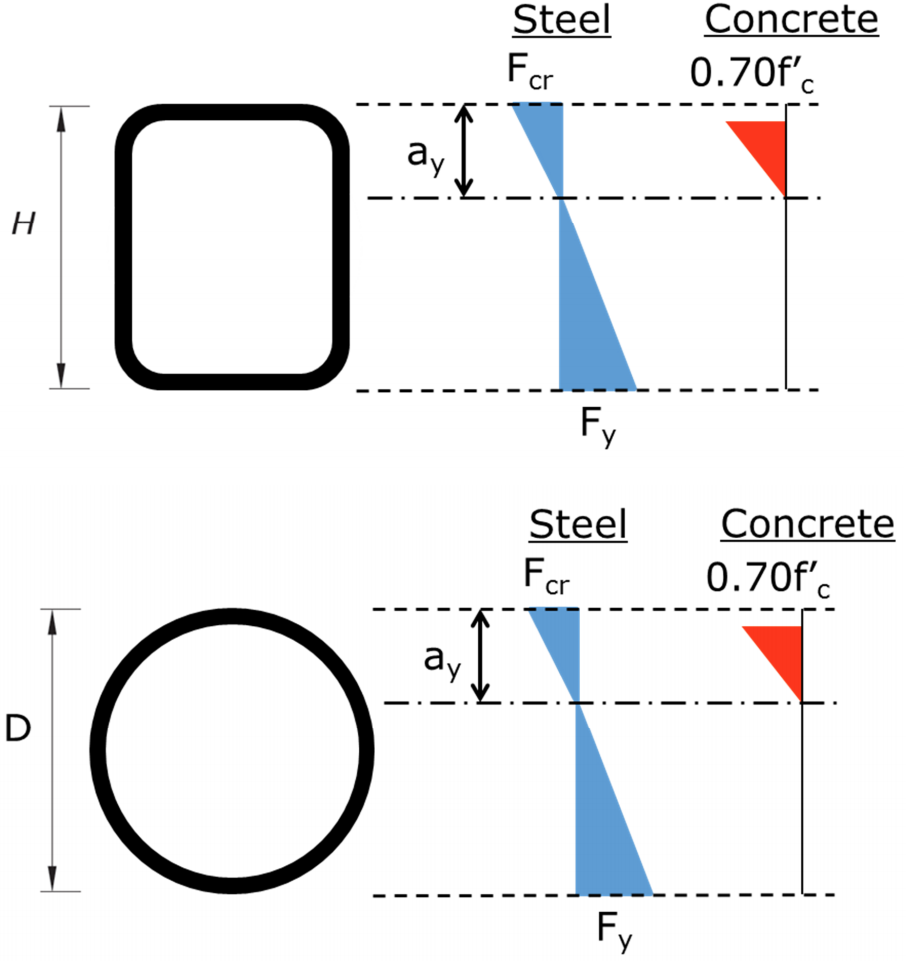
Note that parts (b) and (c) utilize the strain compatibility method with assumed stress-strain relationships for steel and concrete – along with limitations on the maximum strains for each. Even though the latter may not be evident.
Combined Axial Force and Flexure – I5
One of two approaches are allowed for filled composite members with compact sections; interaction equations of H1.1 or one of the methods of Section I1.2. For members with noncompact or slender sections the equations of H1.1 must be used.
Equations of Section H1.1
The axial and flexural strengths as discussed above are used in the equations of H1.1. According to the Commentary to Section I5, using Section H1.1 is a conservative assessment of the interaction and is more conservative as the contribution of the concrete to the overall strength increases. This is relatively straight-forward method that only requires the calculation of two points (pure bending and pure axial).
Plastic Stress Distribution Method
The second method of creating interaction curves based on the plastic stress distribution method only applies to compact sections. According to the AISC 360-10 Commentary, this is due to lack of research to validate the approach for sections that are not compact. In this method, the interaction curve is created that includes section strength, length effects, and bending and compression resistance or safety factors. Length effects need only be considered for axial loads for HSS sections. Pno represents the cross section compression strength and Pn includes the effects of the column slenderness (i.e. length). The reduction applied to the axial strength for length effects is therefore Pn/Pno. This reduction is taken on the axial strength calculated at each point in the interaction curve.
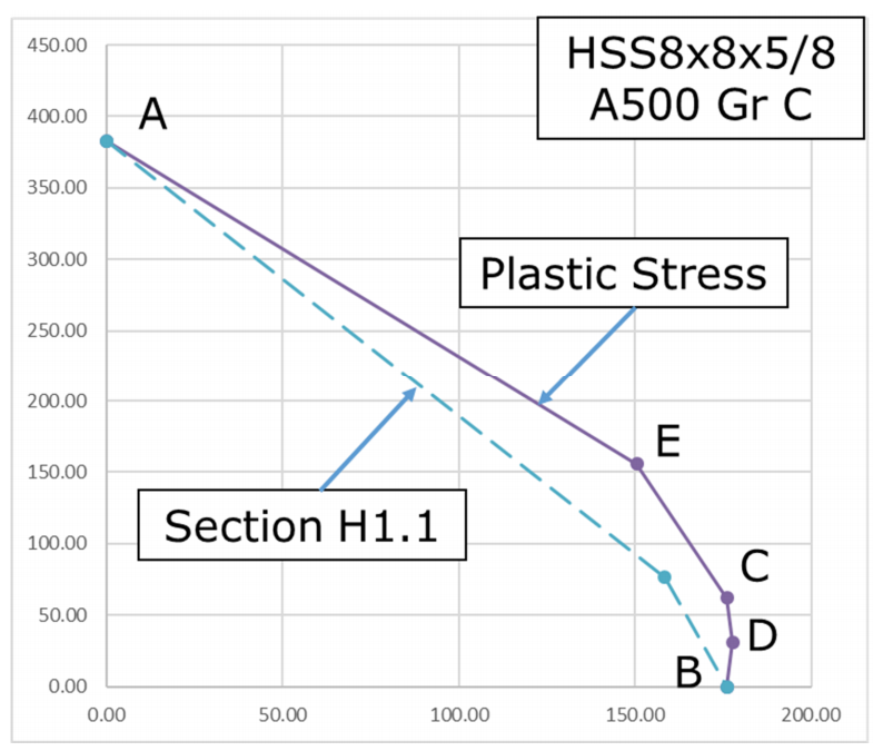
Equations for calculating the interaction curves for round and rectangular HSS sections are given in the discussion by Louis F. Geschwindner listed in the recommendations of this article and can also be found in the AISC Design Examples. There are five points along the curve included, A-E. Figure 6 indicates these points. Point A represents pure axial load and Point B represents pure flexure. Point C represents the point where the moment is equal to the pure bending strength, but has a non-zero axial load. Point D represents the location where the axial load is one-half that determined at Point C. The moment at Point D will be larger than the pure bending moment. Care must be taken in the region between Points B and C. The resistance or safety factor in this region must be applied with care because additional flexural strength may be permitted at a lower axial compressive strength than predicted by the cross section of the member. This can be conservatively avoided by removing Point D.
Figure 6 shows the interaction curves for an HSS8x8x5/8 of ASTM A500 Gr C, comparing the curves from the plastic stress distribution method and the equations from Section H1.1. The H1.1 equations are conservative for all values. For values of high moment, using the H1.1 equations result in significantly lower available axial strengths. (It can also be said that at low axial loads, a significantly higher available moment strength results from the plastic distribution method.) For example, at a moment equal to the available moment strength (ϕMn and Mn/Ω) the interaction curve will allow for an axial load of about 600 kips, whereas the equations of H1.1 would have available axial load of 0 kips. There is significant additional calculated available strength to be gained by using the plastic stress distribution method and may be worth the extra effort.
Shear and Tension
The tensile strength of the composite sections is based on the steel section yielding as given in Section I2.2c. In Section I4.1, the shear strength of composite members is taken as the shear strength of the steel section alone as specified in Chapter G.
Effect of f’c on overall strength
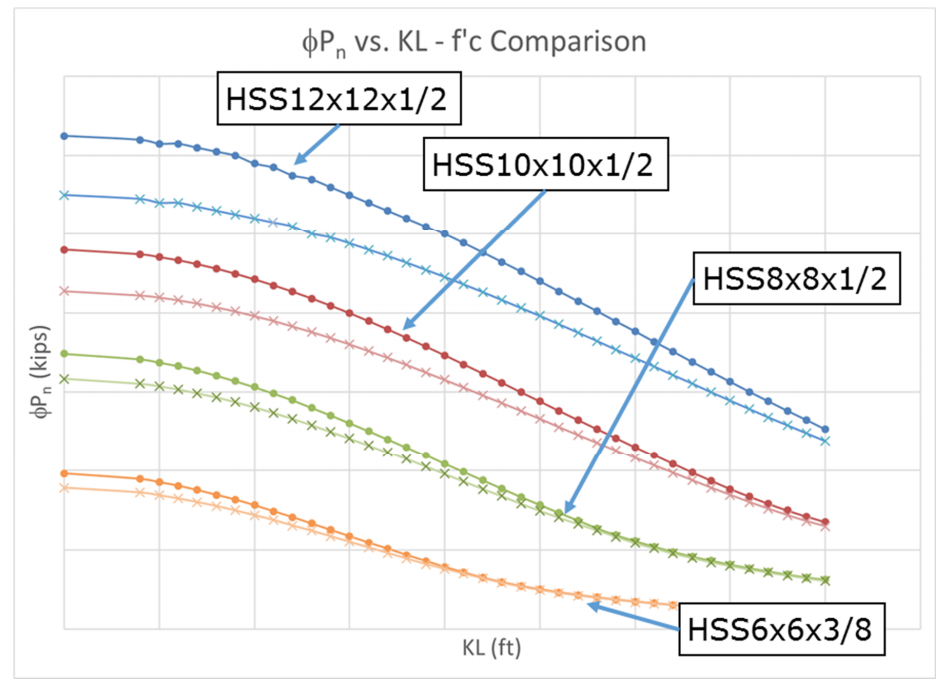
As indicated in the recommendations of this article, the effect of f’c on the overall strength of the composite section is limited. As can be seen in Figures 7 and 8, increasing concrete strength from f’c of 4 ksi to 6 ksi does not increase the axial strengths by more than about 10%. Figure 7 includes a common range of section sizes (12 in. to 6 in.) and indicates that the largest increases are for the larger sections (with more concrete in proportion to the total composite area) and at smaller values of KL. Note that areas where the curves for the different f’c values converge is where the steel section strength controls.
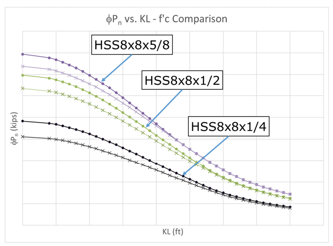
Figure 8 focuses on an HSS8x8 to illustrate the effect of the wall thickness. From this comparison (and similar ones not shown) the largest effect is seen in the thinner walls.
Resources
The Steel Tube Institute’s HSS Design Manual series has invaluable information on the design of HSS members. Volume 2A covers member design for columns and includes a discussion on composite columns. There are load tables (ϕPn, Pn/Ω) for ASTM A500 Grade C and ASTM A1085 columns with f’c = 4 ksi. The tables also include the available flexural strength (ϕMn and Mn/Ω) for each section. Using these values and the interaction equations in H1.1, all information required for design of beam-columns is available. The AISC Steel Construction Manual, 14th Ed. has similar tables for A500 Gr B columns.
November 2016