STI Limit State Table Derivations
The derivations shown below are intended to demonstrate the equivalence of limit state equations between the current AISC 360-22 Specification and 16th Ed. Manual Part 9 with the prescriptive tables that were previously shown in AISC 360-10 Specification Chapter K.
The following limit state derivations are included:
- 1) Limit State = Local Yielding of HSS Chord Sidewalls
- STI Limit State Table = Moment Table
- Connection = Rectangular HSS-to-Rectangular HSS under In-Plane Moment
- 2) Limit State = Local Yielding of Branches Due to Uneven Load Distribution
- STI Limit State Table = Moment Table
- Connection = Rectangular HSS-to-Rectangular HSS under In-Plane Moment
- 3) Limit State = Local Yielding of HSS Chord Sidewalls
- STI Limit State Table = Moment Table
- Connection = Rectangular HSS-to-Rectangular HSS under Out-of-Plane Moment
- 4) Limit State = Local Yielding of Branches Due to Uneven Load Distribution
- STI Limit State Table = Moment Table
- Connection = Rectangular HSS-to-Rectangular HSS under Out-of-Plane Moment
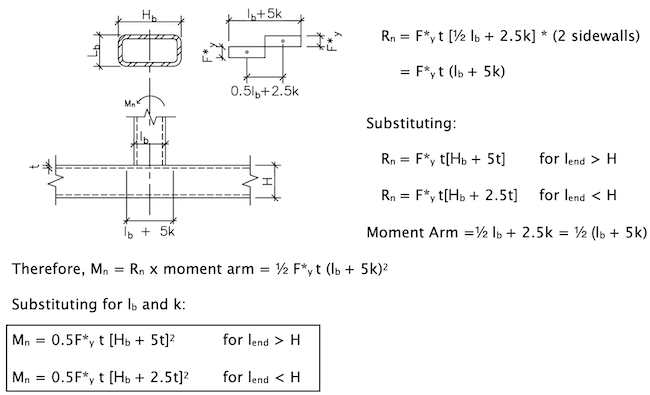
1) Limit State: Local Yielding of HSS Chord Sidewalls | In-Plane Moment for Rectangular HSS (Refer to Moment Limit State Table M2)
Refer to AISC 360-10 Eqn K3-7:
Mn = 0.5F*y t (Hb + 5t)2 [AISC 360-10 Eqn K3-7]
Refer to AISC 360-22 Specification Section J10.2 to derive available strength to match AISC 360-10 Eqn K3-7, based on local yielding of rectangular HSS Sidewalls under in-plane moment.
Rn = Fywtw(5k + lb) For lend > H [AISC 360-22 Section J10.2]
lb = Hb
tw = tdes of HSS chord = t
k = t Consider a conservative 1:1 slope for dispersion in lieu of k = 1.5t.
F*y = Fy for HSS T-Connections
= 0.8Fy for HSS Cross-Connections
2 Sidewalls
Φ = 1.00, Ω = 1.50
Per Cidect Design Guide 3, pp. 62, moment derived from 2 stress blocks can be represented as:
2) Limit State: Local Yielding of Branches Due to Uneven Load Distribution | In-Plane Moment Conn for Rectangular HSS (Refer to Moment Limit State Table M2)

Refer to AISC 360-22 Specification Section F7 to derive available strength to match AISC 360-10 Eqn K3-8, based on local yielding of rectangular HSS branches due to uneven load distribution under in-plane moment.
Mn = FyZeff [AISC 360-22 Eqn F7-1]
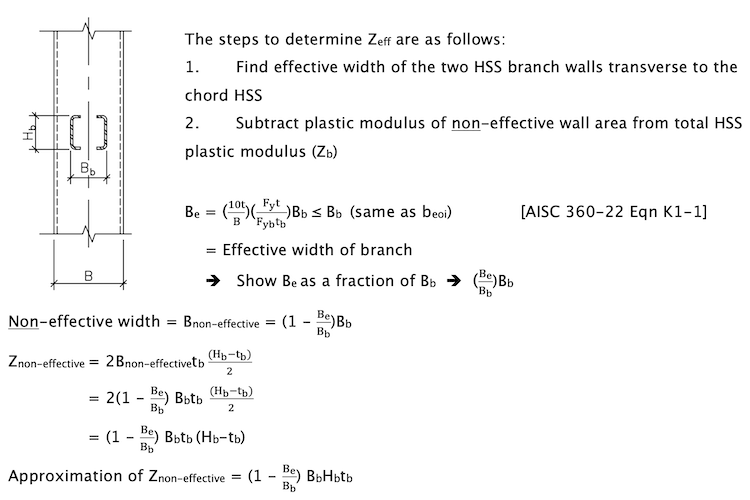
(The approximation ignores the HSS thickness in the last term only which results in a conservative value that underestimates Zeff)

Since the branch member is primarily an axial member rather than a flexural member, the following resistance/safety factors are applied for this limit state:
Φ = 0.95, Ω = 1.58
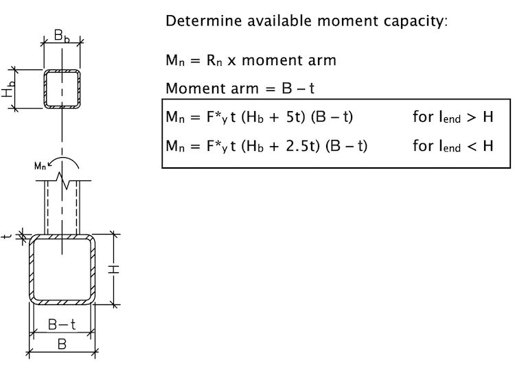
3) Limit State: Local Yielding of HSS Chord Sidewalls | Out-of-Plane Moment for Rectangular HSS (Refer to Moment Limit State Table M2)
Refer to AISC 360-10 Eqn K3-10:
Mn = F*y(B – t) (Hb + 5t) [AISC 360-10 Eqn K3-10]
Refer to AISC 360-22 Specification Section J10.2 to derive available strength to match AISC 360-10 Eqn K3-10, based on local yielding of rectangular HSS Sidewalls under out-of-plane moment.
Rn = Fywtw (5k + lb) For lend > H [AISC 360-22 Section J10.2]
tw = tdes of HSS chord = t
k = t Consider a conservative 1:1 slope for dispersion in lieu of k = 1.5t.
lb = Hb / sinθ For θ = 90, lb = Hb
F*y = Fy for HSS T-connections
= 0.8Fy for HSS Cross-Connections
Substituting to determine available strength:
Rn = F*y t [5t + Hb] = F*y t (Hb + 5t) for lend > H
Rn = F*y t [5t + Hb] = F*y t (Hb + 2. 5t) for lend < H
Φ = 1.00, Ω = 1.50
4) Limit State: Local Yielding of Branches Due to Uneven Load Distribution | Out-of-Plane Moment Conn for Rectangular HSS (Refer to Moment Limit State Table M2)

Refer to AISC 360-22 Specification Section F7 to derive available strength to match AISC 360-10 Eqn K3-11, based on local yielding of rectangular HSS branches due to uneven load distribution under out-of-plane moment.
Mn = FyZeff [AISC 360-22 Eqn F7-1]
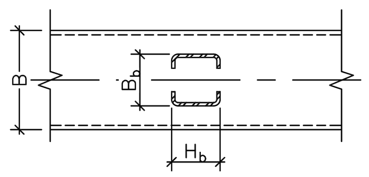
The steps to determine Zeff are as follows:
- Find effective width of the two HSS branch walls transverse to the HSS chord
- Subtract plastic modulus of non-effective wall area from total HSS plastic modulus (Zb)
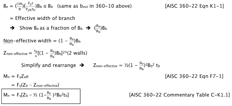
Since the branch member is primarily an axial member rather than a flexural member, the following resistance/safety factors are applied for this limit state:
Φ = .95, Ω = 1.58
STI Limit State Tables Per AISC 360
STI's free Limit State Tables have been updated to the AISC 360-22 Specification and 16th Edition Manual. These tables serve as a comprehensive guide to the HSS limit state checks required for a wide range of HSS connection conditions and loading scenarios, including shear, axial, moment and truss connections. This invaluable resource also serves as an excellent companion to STI's Spreadsheet Design Tools.