Shear Lag in Slotted-End HSS Welded Connections
By Jeffrey A. Packer
Bahen/Tanenbaum Professor of Civil Engineering, University of Toronto, Ontario, Canada
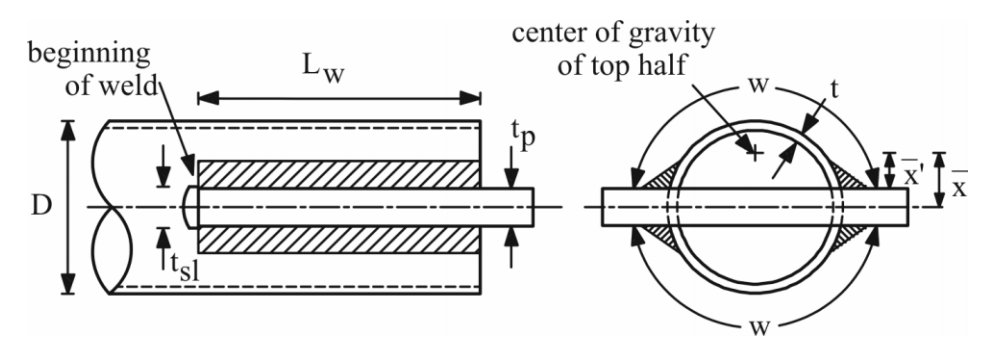
A very popular and simple HSS connection, especially at the ends of diagonal bracing members, involves a gusset plate fillet-welded into a slot in the HSS, as shown in Figure 1 for a round HSS. Typically, in the U.S., the HSS is “over-slotted” to accommodate site adjustment and field welding, thus there is often a hole in the HSS beyond the end of the gusset plate, creating a net section which is less than the gross cross-sectional area of the tube (see Figure 1). This insertion method does allow the single gusset plate to be concentric with the HSS axis, however.

When loaded in axial tension, this type of connection is liable to fail by fracture failure modes that are relatively brittle. Extensive experimental and numerical (Finite Element analysis) research has been performed and it has been shown that the connection behavior depends on the length of plate insertion into the slot, or the length of weld (Lw in Figure 1). With a long weld length, the full capacity of the HSS can be attained; for a net section (with an open slot) this means that an ultimate strength of AnFu can be attained, where An is the net cross-sectional area of the HSS. For shorter weld (insertion) lengths, the cross-sectional capacity is reduced by shear lag and the ultimate connection capacity is given by AeFu, where Ae is an effective net area given by:
Ae = AnU AISC 360-10 Eqn. (D3-1)
Equation 1
and U is a shear lag factor ≤ 1.0. The nominal capacity for tensile rupture in the net section is then:
Pn = FuAe AISC 360-10 Eqn (D2-2)
Equation 2
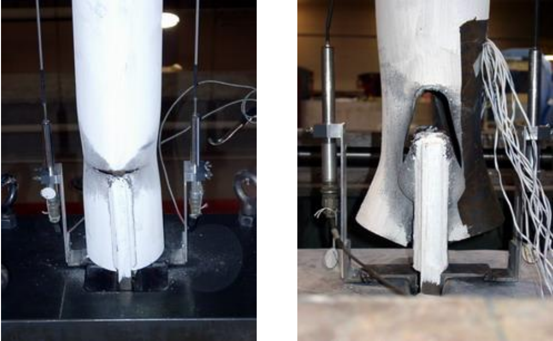
This tensile limit state is still manifested by a failure mode in which circumferential fracture of the HSS occurs (see Figure 2(a)). For even shorter weld (insertion) lengths, the failure mode changes to “block shear”, wherein the gusset plate tears out of the HSS by forming a fracture path through the HSS wall (on two opposite sides of the HSS) immediately adjacent the fillet weld toes. This tensile limit state is illustrated in Figure 2(b). A small part of the failure path involves tensile rupture of the HSS walls (where the failure path is perpendicular to the tensile force in the gusset plate, indicated by “beginning of weld” in Figure 1), and most of the failure path involves shearing of the HSS walls (where the failure path is parallel to the tensile force in the gusset plate). The nominal capacity for block shear rupture can be calculated by AISC 360-10 Chapter J Eqn. (J4-5).

Design of this connection type thus involves calculating the member tensile capacity according to AISC 360 Chapter D2, with consideration for the effect of shear lag (Chapter D3), and also calculating the welded connection tensile capacity according to AISC 360 Chapter J4.3. Shear lag reduction factors, U, are given in AISC 360 Table D3.1, for both round and rectangular HSS with a single concentric gusset plate, but only for Lw ≥ H or D (the HSS width parallel to the gusset, or HSS diameter), as:

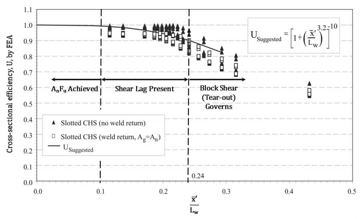
This limited information tends to discourage connections with Lw < H or D. When Lw > 1.3D, for round HSS, Table D3.1 states that U = 1.0 (i.e. no shear lag effect). This has been confirmed by Martinez-Saucedo and Packer (2009), but Table D3.1 does create a discontinuity for U at the break between Lw > 1.3D and Lw < 1.3D. Research has shown that there is a gradual transition in behavior for this connection type, depending on the amount of plate insertion (weld length), which is illustrated in Figure 3. This figure shows the shear lag reduction factor, U, for round HSS (CHS), with and without weld returns at the end of the gusset plate, versus a non-dimensionalized insertion (weld) length. The solid curved line in Figure 3 represents the best fit to the numerical test data and is given mathematically by USuggested in that figure. The term x̄’ was introduced to emphasize that the eccentricity that should be considered in the shear lag expression is best measured from the face of the gusset plate (rather than the middle of the gusset plate). This adjusted dimension to the center of gravity of the half-tube (see Figure 1), which is tp /2 less than in AISC 360 Table D3.1, better represents the performance of connections where the gusset plate is thick relative to the HSS size. This new, continuous formula for U was also shown to be applicable to slotted HSS connections made with rectangular, square and elliptical hollow sections (Martinez-Saucedo and Packer, 2009). Another feature of this research was confirmation that the HSS slots did not need to be extremely smooth, provided that the welded connection was subject only to predominantly static loading.

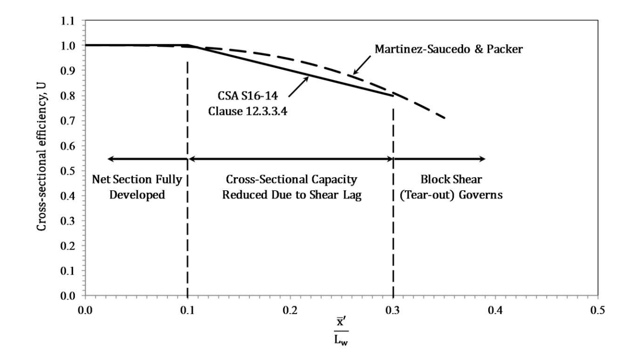
In the latest edition of the Canadian limit states steel design standard, CSA S16-14 (CSA, 2014), a new clause 12.3.3.4 has been added to specifically address the shear lag factor, U, for all slotted HSS welded connections with a single concentric gusset plate, based on the above research. A bi-linear, conservative version of the curve in Figure 3 was taken for CSA S16-14, where:


This bi-linear approximation to the curve in Figure 3, given by Equations (4) and (5), is shown in Figure 4. Although Figure 3 indicates that the limit state of block shear governs for x̄’ /Lw > 0.24, whereas Figure 4 shows the range as x̄’ /Lw > 0.30, one must recall that there are no ranges to the application of the block shear check, in either CSA S16-14 or AISC 360-10, so block shear capacity would actually be calculated for all insertion (weld) lengths. Thus, using the simplified application of Equations (4) and (5), at present, a designer would be making a theoretically redundant calculation for HSS cross-sectional fracture in the range 0.24 < x̄’ /Lw ≤ 0.3.

References
AISC. 2010. “Specification for Structural Steel Buildings”, ANSI/AISC 360–10, American Institute of Steel Construction, Chicago, IL.
CSA. 2014. “Design of Steel Structures”, CSA S16-14, Canadian Standards Association, Mississauga, ON, Canada.
Martinez-Saucedo, G. and Packer, J.A., 2009. “Static Design Recommendations for Slotted End HSS Connections in Tension”, Journal of Structural Engineering, American Society of Civil Engineers, Vol. 135, No. 7, pp. 797-805.
June 2014