HSS Limits of Applicability
By Mike Manor, PE, MLSE
Technical Consultant, Steel Tube Institute
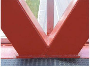
Anyone new to designing structural steel connections involving HSS members may be surprised and a bit confused by the various limit state equations listed in the AISC Steel Specification tables, within Chapter K, that are unique to HSS. Secondly, when engineers turn the page, they discover yet another table that denotes a list called the “limits of applicability” (LOA) for the aforementioned limit state equations. Furthermore, certain limits of applicability apply only to specific HSS connection types. This article will attempt to demystify the limits of applicability for HSS connections and streamline the required limits for the design engineer to understand why the limits exist and when to apply each one.
Limits of Applicability and Why We Need Them
Within the AISC Specification, the equations listed in Chapter K for each limit state are primarily based on empirical laboratory testing. It is not feasible to test all connection conditions for the wide range of available HSS member sizes and thicknesses for both round and rectangular shapes. The test data covers as wide a range of connection configurations and HSS sizes as possible within the resources available. The equations developed from the available data are only valid within the range of the testing. Outside of this range, it is possible that the equations may predict limit state capacities but may also become unconservative in some cases. To ensure the safety of the general public, it is then prudent to limit the range in which these equations are valid to the range of the data sets available, also known as the “limits of applicability.”
The research on HSS connections has uncovered several possible modes of failure that limit the capacity of the connection. However, within certain connection parameters, not all limit states are likely to be the controlling case. For instance, when designing a round HSS K-connection, AISC 360-16 Specification Table K3.1 lists chord plastification as the only limit state that needs to be checked for connections within the limits of applicability in Table K3.1A. Another example is in AISC 360-16 Specification section K3 for HSS truss connections. When truss branches are welded to the chord and joint eccentricities fall within the LOA, then moments resulting from eccentricity of the connection may be ignored. In a way, the LOA can simplify the job of the design professional since the researchers have deemed the remaining failure modes as nongoverning. However, for connections falling outside the LOA, the connection is not prohibited by the AISC Specification but will require engineering judgment and verification to make sure all possible limit states have adequate capacity. Additionally, connections outside of the LOA may result in lower joint efficiencies.
HSS Design Requirements Within AISC 360-16
In previous versions of the Specification, all limit states for HSS connections were contained within Chapter K. In reality though, many of the limit states were actually redundant with the connection limit state equations listed in Chapter J. Thus, AISC decided to remove those limit states from Chapter K and revise the title to “Additional Requirements for HSS and Box-Section Connections.” The last sentence of the first paragraph in Chapter K says “the requirements of Chapter J also apply,” which links the design of HSS connections to both chapters. An important point to note is that Chapter J does not have any limits of applicability because the equations are analytical solutions rather than empirically derived from test data. This means limit states covered by Chapter J can be used for all connection cases, but this also means that all applicable Chapter J limit states must be considered for all connections. For rectangular HSS connections only, there are several sections in Chapter K that direct engineers to design the connections per limit states in Chapter J, including Sections K1, K2.3, K3.3, K4.3 and K5. Chapter K Sections pertaining to round HSS do not reference Chapter J.
When reviewing the limit states required by Chapter K, the LOA do still need to be checked per the relevant table. The first question is then, “What happens when the connection falls outside of these limits?” Section K1 specifically notes that these connections are not prohibited but must be designed by rational analysis. User notes in Sections K3.3 and K4.3 advise the engineer that when a connection falls outside of the LOA, Chapter J still applies but limit states in Chapter K are no longer defined and cannot be used directly for design. The good news is the Commentary to Chapter K does at least provide a list of the limit states that need to be considered, but they need to be checked with rational analysis without further guidance.
Sometimes, a connection may not meet the requirements of a single connection type. If the loads in a truss connection are out of balance by more than 20%, then the connection must be checked, for example, as both a K-connection and as a Y-connection. When this happens, the LOA for both types of connection must be checked as well as all applicable limit states from both connection types. There is more explanation and guidance for these scenarios in Specification Section K3 and Commentary Figure C-K1.1.
LOA Categories

When looking through the LOA tables in chapter K, it takes a bit of time to verify which LOA checks are required based on the connection type under consideration. Additionally, with each table having a different number of requirements (with only some overlap) and round HSS having different LOA than rectangular, understanding the limits can be difficult. For better understanding, the LOA can be divided into categories, which include material properties, slenderness and connection geometry.
Material Properties
Material property requirements are the easiest place to start since they are universal through all connection types for both rectangular and round shapes. Table 1 lists these requirements. The tables in this article list the round HSS requirements on the left and rectangular HSS on the right. The maximum yield strength of all materials tested is 52ksi, hence the limit. The reason for the maximum ratio of the material yield to tensile strength is to ensure ample connection ductility in cases where strength formulas based on yield stress govern the design. Two examples are punching shear and branch local yielding. When the material ratio is higher, there is an increased likeliness of fracture failure modes occurring at lower-than-expected connection forces. There is one exception to this rule for ASTM A500 Grade C material, which has a ratio of 50 ksi / 62 ksi = 0.806 for rectangular HSS. The testing this information is based on was compiled over many decades. During most of that time, grade C was not as common as it is now, which is why it falls outside of the testing limit. However, a portion of ASTM E29 called the “rounding method” covers significant digits and a method for rounding values in ASTM. Since the limit of 0.8 only has one significant figure, the ductility ratio only needs to be rounded to one significant figure, thus the rounded value of 0.8 for ASTM A500 Gr C is deemed acceptable per the rounding method. The final material property limit for HSS is a minimum distance from the end of the chord member. When the connection is too close to the end of the member, the yield line patterns assumed for the limit states cannot form as intended, thus invalidating the capacity equation. The connection must either meet the end distance requirement or add a welded cap plate to the end of the HSS member to replace the missing stiffness.
Slenderness
Slenderness of HSS members is another important attribute of HSS with a significant effect on connection joint strength when under compression loading. Refer to Tables 2A through 2D. The strength of a connection joint increases as both the chord slenderness width-to-thickness ratio (D/t and B/t) decreases and branch-to-chord width ratio (Db/D & Bb/B) increases. The overall slenderness then becomes a balance between a low slenderness ratio (stocky section) for the connection and a high slenderness ratio (thin section) for economy of global buckling strength. Typically, relatively stocky sections will be chosen to satisfy the connection force demand. For the case of tension loading, per global design, the slenderness ratio will likely be high, but for the joint connection, it is recommended that the slenderness ratio be as small as possible to help minimize fabrication costs.
Connection Geometry
Connection geometry covers the relationship between members within the same connection. There are different LOA requirements depending on the connection type, as shown in Tables 2A through 2D. T-, Y- and Cross-connections only need to look at the branch-to-chord width ratio while K-connections add a few more requirements. The branch-to-chord width ratio has a minimum point where the relative HSS sizes become impractical for the loads present, thus the requirement for the minimum width ratio LOA.
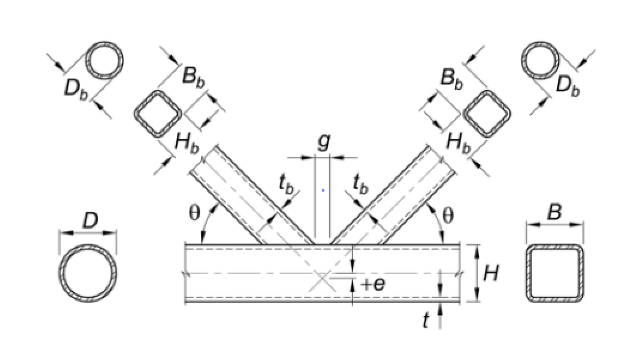
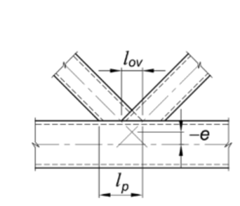
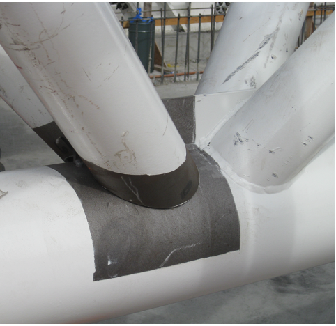
Gapped and overlapped K-connections each have their own unique LOA requirements compared to other connection types, but they do share one in common. Refer to Tables 2C and 2D. The minimum ratio of joint eccentricity to chord height (e/H) is -0.55 with a maximum of +0.25. As shown in Figures 3 and 4, a negative eccentricity locates the work point of the two branches above the chord centerline while a positive eccentricity work point is below the centerline. When the joint eccentricity is within this range limit, then the calculated joint capacity can ignore the induced moments from the eccentricity based on the results of the testing that these equations are based on as there is minimal effect on capacity. Should a gapped K-connection fall outside of the eccentricity limit, then the K-connection should be viewed as two separate Y-connections.
There are a few more specific LOA for gapped K-connections that are based on the geometric relationship between both branch sizes, the chord size and the width of the gap between branches. See Table 2C. For round HSS, the minimum width ratio of 0.4 is to prevent unconservative plastification capacities[1] that surfaced during testing. For rectangular HSS, if both branches are square but different sizes, then the smaller width must be more than 63% of the larger width. The minimum gap width is to ensure adequate space for welding both branches during the fabrication process. There are specific LOA involving an effective width based on the perimeter of both branches, beff, as well as a chord slenderness ratio, ɣ. All of these variables have been defined in 360-16 and are included in Table 2C.
Switching to overlapped K-connections, these also have LOA requirements based on the relationship of the widths and thicknesses between both branches and the chord. The overlapped branch (j) must be at least as thick as the overlapping branch (i). This requirement is the same for both round and rectangular HSS, but in 360-16, the equations are presented in slightly different forms. In rectangular HSS connections, the overlapping branch width must be at least 75% of the overlapped branch width. There is also a minimum 25% overlap between the two branches to ensure adequate interconnection of the branches for the shear loads (horizontal component of the branch axial force) to directly transfer from one branch to the other.
Global Force Strength Reduction, Qf
The final limit of applicability is not directly given within the 360-16 specification. If the global forces in the chord at the location of the connection are large and under compression, they actually reduce joint connection capacity. That is where the value of Qf comes into play to account for this capacity reduction. For connection limit states pertinent to 360-16 Chapter K, the equation to calculate Qf is given directly in the design tables. However, when reviewing limit states such as plastification on rectangular members per Specification Section J10.10, the User Note points to part 9 of the 15th Edition Steel Manual. Page 9-15 provides guidance for the value of Qf, but it is important to be aware of the limit of applicability for rectangular HSS members that this equation for Qf is only valid when the ratio is satisfied.
LOA Summary Tables
When reviewing a connection for the pertinent limits of applicability, there are many requirements that can be ignored because they are for a different connection type. Looking through all of these extra LOA requirements takes time to make sure the correct requirements have been considered without missing any. The LOA are important for both the engineer of record and the connection engineer for projects when the connection design is delegated to a third party. These LOA must be considered at the time the framing members are designed so as not to limit the ability of the connection designer or to make rational analysis required. To help clarify all specific requirements, below are tables summarizing the LOA separated out for each specific connection type. On the left side are the requirements for round HSS, and on the right are the requirements for rectangular HSS. Table 1shows the LOA requirements that are common to all connection types. Therefore, to satisfy the LOA for each specific connection type, Table 1 must be used in conjunction with Tables 2A-2D.
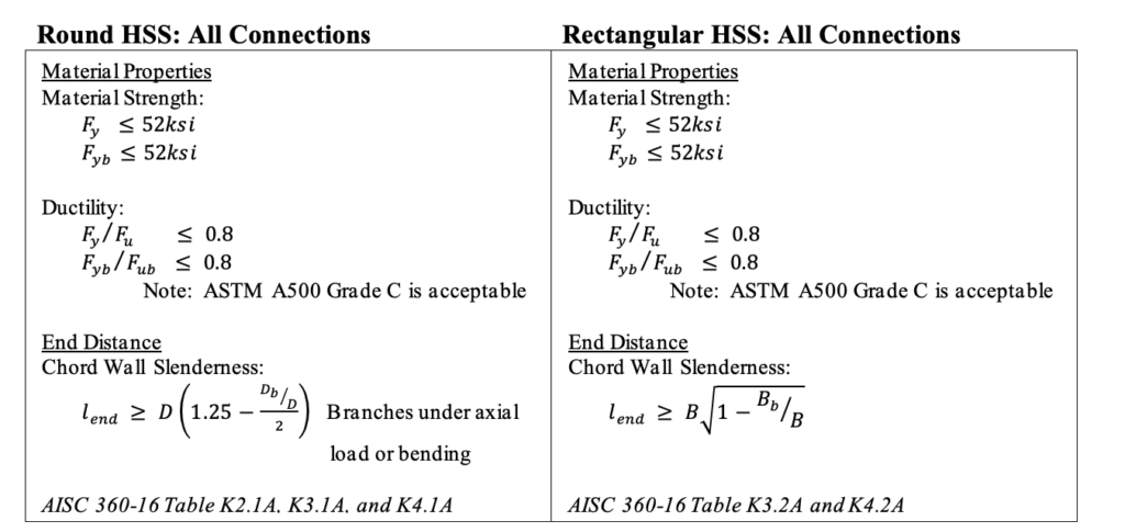
Note: For plate to round HSS connection end distance, replace Db with plate width Bb.
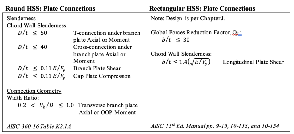
Notes: 1) Reference Table 1 for additional limits applicable to all HSS connections.
2) Plate connections include transverse plates, longitudinal plates, and longitudinal-through plates unless otherwise noted in Table 2A.
3) IP = In-Plane OOP = Out-of-Plane
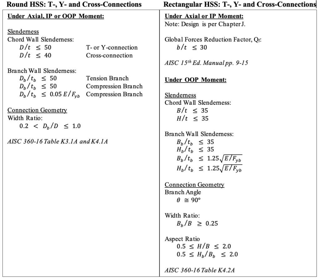
Note: Reference Table 1 for additional limits applicable to all HSS connections.
IP = In-Plane OOP = Out-of-Plane
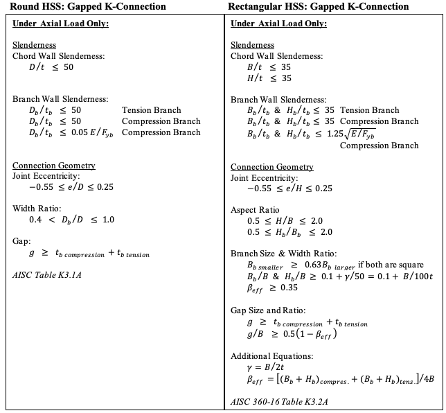
Note: Reference Table 1 for additional limits applicable to all HSS connections.
Rectangular HSS
Connection
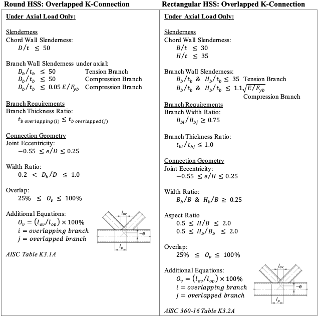
Note: Reference Table 1 for additional limits applicable to all HSS connections.
Concluding Thoughts
Understanding the origins of the limits of applicability for HSS connections can help clarify why they are required. First, they are to help give the connection designer guidance based on the available research. Second, they tell the designer when the equations of Chapter K are not valid and rational analysis is required. Just working through the limits of applicability can be a tedious task, especially if there are multiple connection types on a single project. However, taking the time to go through each limit and listing which connection type they belong to can make a big difference. This article has taken that step for you with an easy quick reference to use the next time you design an HSS connection. Below are additional resources the Steel Tube Institute has developed to navigate the limit state calculations and corresponding limits of applicability:
References
AISC, 2016. “Specification for Structural Steel Buildings,” ANSI/AISC 360-16, and Commentary, American Institute of Steel Construction, Chicago, IL.
AISC, 2017. “Steel Construction Manual, Fifteenth Edition,” American Institute of Steel Construction, Chicago, IL.
Olson, K. (May, 2018). “AISC 360-16, Chapter K,” Steel Tube Institute.
Olson, K. (December, 2019). “Your Questions Answered: AISC 360-16, Chapter K & HSS Connections,” Steel Tube Institute.
Packer, J. (April, 2016). “HSS KT-Connections,” Steel Tube Institute.
Packer, J. (February, 2020). “Connection Design With High-Strength HSS,” Steel Tube Institute.
Packer, J.A., Wardenier, J., Zhao, X.-L., van der Vegte, G.J. and Kurobane, Y. 2009. “Design Guide for Rectangular Hollow Section (RHS) Joints Under Predominantly Static Loading,” CIDECT Design Guide No. 3, 2nd. edition, CIDECT, Geneva, Switzerland.
Wardenier, J., Kurobane, Y., Packer, J.A., van der Vegte, G.J. and Zhao, X.-L. 2008. “Design Guide for Circular Hollow Section (CHS) Joints Under Predominantly Static Loading,” CIDECT Design Guide No. 1, 2nd. edition, CIDECT, Geneva, Switzerland.
February 2022
[1] 360-16 Commentary
ASCE 360-16 Limit State Tables
STI created Limit State Tables to help designers navigate the significant changes to Chapter K in the AISC 360-16 Specification. The tables summarize limit state equations and limits of applicability for your specific connection.