Welded Truss Connections between HSS Branches and I-Shaped Chords
By Jeffrey A. Packer
Bahen/Tanenbaum Professor of Civil Engineering, University of Toronto, Ontario, Canada
There are instances in which designers elect to use planar trusses composed of HSS web members and wide-flange (or I-shaped) chord members. Welded truss-type connections are the result, typically arranged as shown in Figure 1, with branches welded to the chord flange. This “specialty case” is not covered by AISC 360-16 (AISC, 2016), nor by AISC Design Guide No. 24 (Packer et al., 2010). Experimental research has been performed on such hybrid connections (Wardenier and Mouty, 1979; Wardenier, 1982) and it has been shown that, in many respects, the behavior of connections between open sections and hollow sections is comparable to that of connections between rectangular HSS (Wardenier et al., 2010).

Limit States
The possible connection failure modes or limit states for T-, Y-, Cross- and K-connections are: (i) branch failure due to uneven load distribution (leading to premature yielding of a tension branch or a compression branch); (ii) chord web failure (by local yielding); (iii) chord shear yielding; and (iv) chord local buckling. Local buckling of a compression branch member or a compression chord member can be avoided by choosing appropriate diameter-, width- and depth-to-thickness ratios, thus by applying suitable limits of applicability to geometric parameters. These failure modes are shown diagrammatically, for hollow section chord connections, in Fig. C-K3.1 (c) to (f) of the Commentary to Section K3 of AISC 360-16 (AISC, 2016). Note that chord plastification does not occur since this can only take place after excessive yielding of the chord web. Thus, the governing failure modes for HSS branch-to-I shape chord connections can be reduced to: (i) branch failure; (ii) chord web failure; and (iii) chord shear failure (Wardenier et al., 2010).
Limit State of Local Yielding of Branch(es) due to Uneven Load Distribution
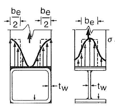
The distribution of stress in the transverse wall of an axially loaded HSS branch member, welded to either an open or tubular section, is generally very non-uniform, as shown in Figure 2. This is particularly so for connections to rectangular HSS chords where the chord wall slenderness (B/t) is high. For all sections the branch peak stress will occur adjacent to the stiff point(s) of the chord connecting face; for an I-shape chord this will be next to the central web, whereas for a rectangular HSS chord this will be next to the two outer webs/corners. For both round and rectangular branch HSS-to-I shape chord connections there will be two portions of branch effective width/length, be, as shown in Figure 3. Hence, the branch nominal strength, Pn, is given by (Wardenier et al., 2010):
Pn=2Fybtbbe
Equation 1
where Fyb is the HSS branch yield stress, tb is the HSS branch design thickness (Figure 1), and

where tw is the I-section chord web thickness (Figures 1 and 2), r is the radius of the web-to-flange fillet (Figure 1), t is the chord flange thickness (Figure 1) and Fy is the chord yield stress. For a rectangular branch, if be > Bb it is conservatively proposed to follow the branch perimeter, as shown in Figure 3(b). The failure criterion of branch local yielding is also used as the design limit state for overlapped HSS K-connection branches welded to an I-section chord, in an analogous manner to rectangular HSS-to-HSS overlapped K-connections (see Table K3.2 of AISC 360-16).


Limit State of Local Yielding of Chord Web
As can be visualized from Figure 3, the branch load transferred to the chord web is – for a rectangular HSS branch – mainly concentrated beneath the transverse walls of the branch (Figure 3(a)), unless the branch is small relative to the chord (Figure 3(b)). An effective length of the chord web, bw, thus resists the branch force, as shown in Figure 4.

The web nominal strength, Pnsin0, is then given by (Wardenier et al., 2010):
Pnsinθ = Fytwbw
Equation 3

where
and Hb is the branch depth, measured in the plane of the connection (Figure 1). This model assumes that the force in a branch transverse wall disperses at a slope of 2.5:1 to the k-line of the I-section (i.e. to a depth of t + r in the chord member), as shown in Figure 4.
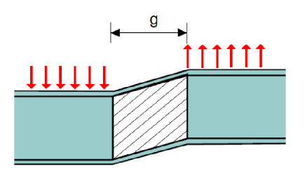
Limit State of Shearing of Chord Cross Section
If a chord member is subject to a shearing force across the member, a failure mode of cross-section shearing is possible, as illustrated in Figure 5. For I-shaped members, the nominal shear strength is specified by Section G2.1 of AISC 360-16 (AISC, 2016) and – for nearly all ASTM A6 W, S and HP shapes with Fy = 50 ksi (a User Note to AISC 360-16 Section G2.1(a) provides the 8 exceptions) – is given by:
Pnsinθ = 0.6FyAv
Equation 5
where A, is the chord shear area, of Htw (see Figure 1).

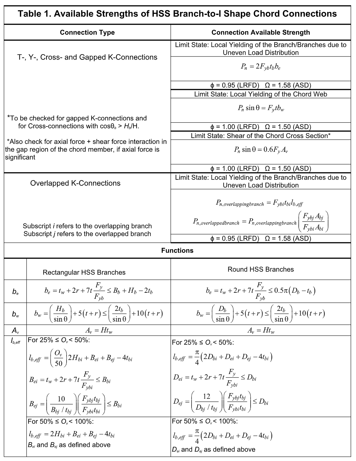
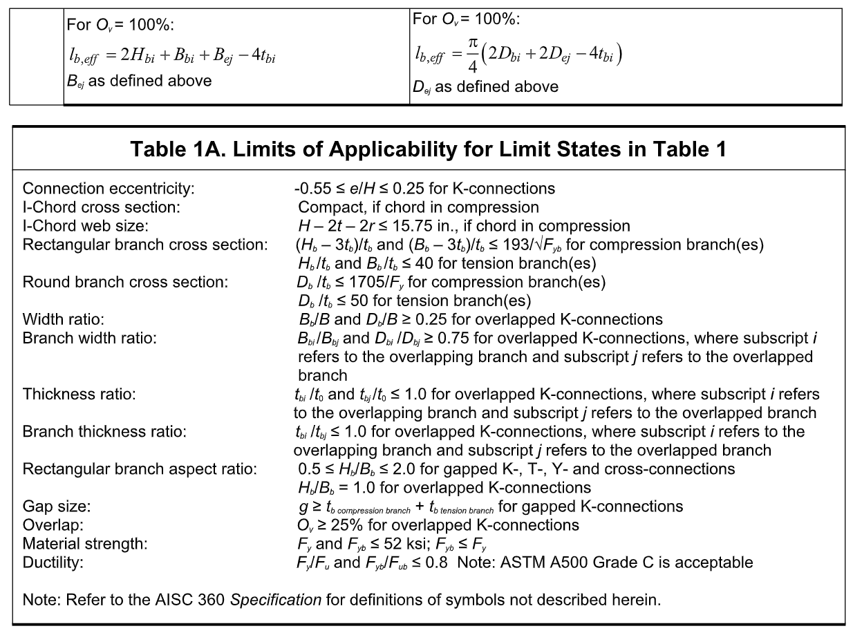
Design provisions for these three limit states, along with the pertinent limits of applicability, per ISO 14346 (2013), are summarized as connection available strengths for LRFD and ASD, in Tables 1 and 1A.


References
AISC. 2016. “Specification for Structural Steel Buildings”, ANSI/AISC 360-16, and Commentary, American Institute of Steel Construction, Chicago, IL.
Davies, G. and Packer, J.A. 1982. “Predicting the Strength of Branch Plate-RHS Connections for Punching Shear”, Canadian Journal of Civil Engineering, Vol. 9, pp. 458-467.
ISO. 2013. “Static Design Procedures for Welded Hollow-Section Joints – Recommendations”, ISO 14346, 1st. edition, International Organization for Standardization, Geneva, Switzerland.
Packer, J.A., Sherman, D. and Lecce, M., 2010. “Hollow Structural Section Connections”, Steel Design Guide No. 24, American Institute of Steel Construction, Chicago, IL.
Wardenier, J. 1982. “Hollow Section Joints”, Delft University Press, Delft, The Netherlands.
Wardenier, J. and Mouty, J. 1979. “Design Rules for Predominantly Statically Loaded Welded Joints with 14346Hollow Sections as Bracings and an I- or H-section as Chord”, Welding in the World, Vol. 17, No. 9/10.
Wardenier, J., Packer, J.A., Zhao, X.L. and van der Vegte, G.J. 2010. “Hollow Sections in Structural Applications”, 2nd. edition, CIDECT, Geneva, Switzerland.
February 2019