Square and Rectangular HSS-to-HSS Moment Connections
By Jason McCormick
Associate Professor, Civil & Environmental Engineering, University of Michigan, Ann Arbor, MI, USA
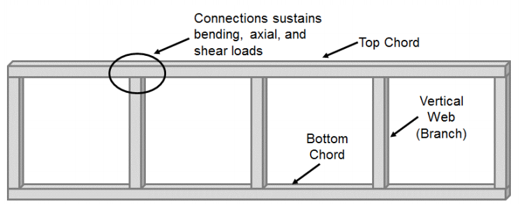
Moment connections made of rectangular and square hollow structural sections (HSS) have received less consideration compared to HSS-to-HSS connections made up of axially loaded members (T-, Y-, cross-, and K-connections). The majority of static studies focusing on these connections have considered Vierendeel truss systems. These systems are often formed by square or rectangular top and bottom chords that are connected with square or rectangular vertical web (branch) members (Figure 1). As a result of this configuration, the chord-to-web connection undergoes significant bending along with shear and axial loads and is not considered a pinned connection as is commonly done in typical truss systems. Originally conceived in 1896 by Arthur Vierendeel, it was not until HSS were developed that the potential for Vierendeel trusses started to be realized (Korol et al. 1977), but their use required an understanding of how to transfer moment between HSS-to-HSS T-connections.
Many of the early studies of these connections focused on the ability of the connection to develop the full moment capacity of the branch member. Jubb and Redwood (1966) showed that when the branch section had an equal width to the chord section (β=1) the full moment capacity of the HSS member could be achieved without reinforcement. However, this study did not consider the potential loss of moment capacity due to the presence of axial load. On the other hand, Korol et al. (1977) showed that connections with a smaller branch width than the chord could not develop the full moment capacity of the branch without reinforcing through a series of 29 different connection tests considering 5 different configurations (unreinforced, branch flange reinforcing plates, chord flange stiffeners, haunch, and truncated pyramid). In general, the strength and rigidity of unreinforced Vierendeel type connections decreases with an increase in chord slenderness ratio (B/t) and decrease in branch-to-chord width ratio (β). As a result, unstiffened Vierendeel truss type connections can only be considered rigid (i.e. undergo minimal relative rotation between the chord and branch) when the branch-to-chord width ratio is 1.0 and the chord slenderness ratio is low or the connection is reinforced (Packer 1993).
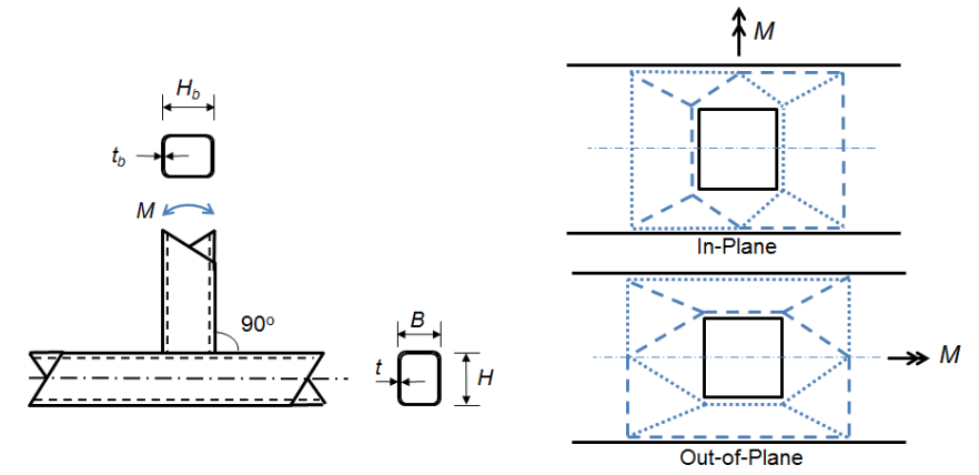
Because the maximum moments in these joints can occur at excessively large deformations, a similar approach to that used for axially loaded square and rectangular HSS joints is adopted, where by an ultimate bearing capacity or a deformation or rotation limit is used to characterize the design moment (Wardenier 1982). AISC 360-10 (Chapter K3) considers three limit states for square and rectangular HSS T-connections under static in-plane bending: chord wall plastification, sidewall local yielding, and local yielding of the branch due to uneven load distribution. Chord wall plastification occurs as a result of the width of the branch member being less than the width of the chord (β ≤ 0.85) requiring the tension and compression loads produced by the bending moment to be transferred through the relatively flexible face of the chord rather than directly to the stiffer sidewalls. The limit state equation (AISC 360-10 Equation K3-6) can be derived from yield line theory (Figure 2):

Mn is the nominal moment capacity of the connection, Fy is the specified minimum yield strength of the chord, Hb is the overall height of the branch, h is the load length parameter equal to the height of the branch divided by the width of the chord (assuming a 90o angle between the chord and branch member as is typical of Vierendeel trusses), and Qf is a parameter to reduce the capacity of the joint in the presence of axial compression in the chord.
The other two limit states are associated with connections where the width of the branch member is equal or almost equal to the width of the chord (β > 0.85) meaning the tension and compression loads developed in the flanges of the branch member are transferred almost directly into the stiffer sidewalls of the chord. The limit state for sidewall local yielding (AISC 360-10 Equation K3-7) of a T-connection can then be derived from the web local yielding equation for concentrated forces applied at a distance from the end of the member greater than its depth (AISC 360-10 Equation J10-2):
Mn = 0.5Fyt(Hb + 5t)2
Equation 2
For local yielding of the branch due to uneven load distribution (AISC 360-10 Equation K3-8) in a T-connection, an effective width approach is used to reduce the capacity of the bracing member to obtain the nominal moment applied by the brace:

Fyb is the specified minimum yield strength of the branch, Zb is the plastic section modulus of the branch about the axis of bending, beoi is the effective width of the branch, Bb is the overall width of the branch, and tb is the design wall thickness of the branch.
Because there is limited experimental evidence to support specific design models for Vierendeel truss connections (T-connections) under out-of-plane bending, analogous limit states as those for in-plane bending are used (Packer et al. 2010). One additional limit state of chord distortional failure develops from the torque applied to the chord by the branch member as a result of the out-of-plane moment. This torque can lead to rhomboidal distortion of the chord. The nominal moment equations for out-of-plane bending can be found in AISC 360-10 Equations K3-9, K3-10, K3-11, and K3-12. The equations for both in-plane and out-of-plane bending of T-connections are similar to those that have been adopted internationally (Packer et al. 2010).
The above design equations were derived considering Vierendeel truss systems under static loads. A recent study (Fadden et al. 2015) has furthered this work to consider the behavior of square and rectangular HSS-to-HSS moment connections under large cyclic loads for use in tube-based seismic moment frame systems (intermediate and special moment frames). Such a system looks to take advantage of the excellent axial, bending, and torsional properties, high strength-to-weight ratio, and architecturally pleasing nature of square and rectangular HSS. The high torsional resistance can lead to a reduction in beam lateral bracing while the high strength-to-weight ratio results in lower seismic mass. However, such connections need to be able to undergo stable plastic hinging of the beam member where 80% of the plastic capacity of the beam member is maintained to either 0.2 rad. (IMF) or 0.4 rad. (SMF) of inter-story drift (AISC 341-10). Given that current seismic design of moment frame systems requires the majority of the inelastic behavior to occur in the beam member, the beam member also must reach its full plastic capacity prior to undergoing local buckling. Fadden and McCormick (2014a) considered both experimental and finite element models to determine limiting width-thickness and depth-thickness requirements for HSS under bending since those specified in the current AISC Seismic Provisions (AISC 341-10) were largely developed based on tests of cyclic axially loaded HSS members.
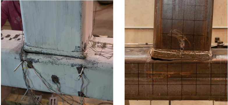
To determine appropriate configuration and detailing requirements to meet this strength and ductility demand, four different connection configurations were experimentally tested: two directly welded unreinforced connections (unmatched and matched) and two reinforced connections (through plate and external diaphragm plate). All of the connections utilized an HSS 10x10x5/8 column. The directly welded connections utilized prequalified CJP welds as specified in AWS D1.1 (2010). For the unmatched connection, the beam was an HSS 12x8x3/8 (β = 0.8) suggesting that plastification of the column face may be a concern. For the matched connection, the beam was an HSS 12x10x3/8 (β = 1.0) allowing the loads to be transferred directly into the sidewall. The AISC loading protocol for prequalification of seismic moment connections was utilized (AISC 341-10) to load the connections. The behavior of the connections was as anticipated with the unmatched connection showing deformation at the column face, while the matched connection was able to transfer the load to the column sidewalls. However, both connection failed due to fracture in the base metal of the column at the toe of the corner of the weld (Figure 3). This brittle failure at rotations of 0.4 rad. and 0.5 rad., respectively, confirmed that directly welded connections do not provide the appropriate behavior for seismic applications.
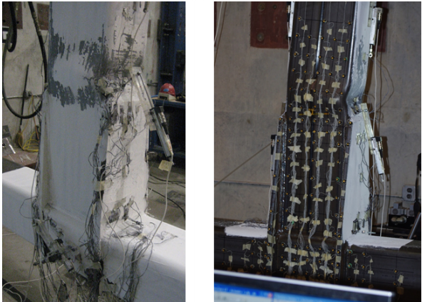
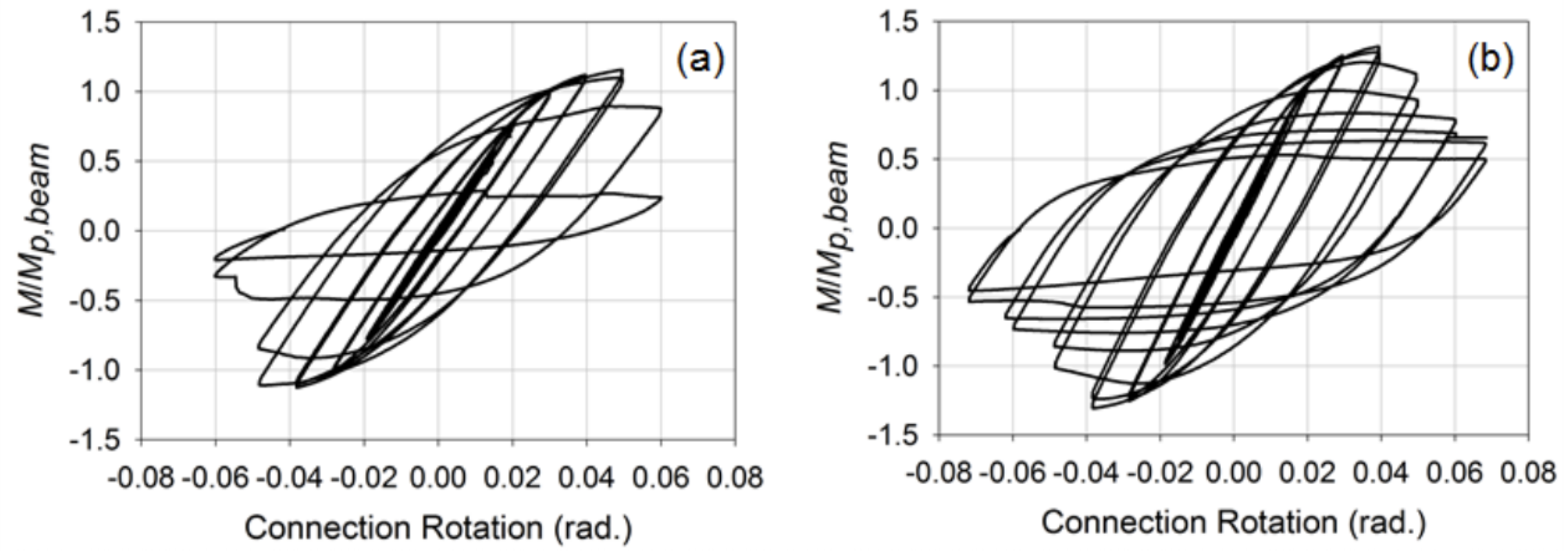
The reinforced connections were then developed considering through plate and external diaphragm plates that are often used in wide flange beam-to-HSS column connections in order to provide a better mechanism to transfer the tension and compression forces to the sidewall of the column and minimize stress concentrations placed on the welds. For these connections, the beams were HSS 12x8x3/8 (β = 0.8) members. Information in regards to the specific procedure used to design and detail these connections can be found in Fadden and McCormick (2014b) and Fadden et al. (2015). Placed under the same loading as the unreinforced connections, the connections showed a more stable behavior with the plastic hinge occurring away from the column face at the end of the through or external diaphragm plate (Figure 4). Both connections also were able to reach 0.4 rad. of rotation prior to undergoing local buckling which resulted in degradation of the moment capacity. However, fracture did initiate at the corner of the HSS beam due to cycling at large rotation levels of 0.7 rad. A comparison of the normalized moment-rotation curves for the matched and external diaphragm plate connections can be seen in Figure 5. Overall, the reinforced connections showed promise for use of HSS-to-HSS seismic moment frame systems, but more work is need to move these connections toward eventual prequalification.
References
AISC. (2010). “Seismic Provisions for Structural Steel Buildings”. ANSI/AISC 341-10. American Institute of Steel Construction, Chicago, IL.
AISC. (2010). “Specifications for Structural Steel Buildings”. ANSI/AISC 360-10. American Institute of Steel Construction, Chicago, IL.
AWS. (2010). “Structural Welding Code”. ANSI/AWS D1.1, American Welding Society, Miami, FL.
Fadden, F. and McCormick, J. (2014a). “Finite Element Model of the Cyclic Bending Behavior of Hollow Structural Sections”. Journal of Constructional Steel Research, 94, 64-75.
Fadden, F. and McCormick, J. (2014b). “HSS-to-HSS Seismic Moment Connection Performance and Design”. Journal of Constructional Steel Research, 101, 373-384.
Fadden, F., Wei, D., and McCormick, J. (2015). “Cyclic Testing of Welded HSS-to-HSS Moment Connections for Seismic Applications”. ASCE Journal of Structural Engineering, 141(2), 04014109-1-14.
Jubb, J.E.M. and Redwood, R.G. (1966). “Design of Joints to Box Sections”. The Institution of Structural Engineers, Conference on Industrialized Building and the Structural Engineer, Institute of Structural Engineers, London.
Korol, R.M., El-Zanaty, M., and Brady, F.J. (1977). “Unequal Width Connections of Square Hollow Sections in Vierendeel Trusses”. Canadian Journal of Civil Engineering, 4, 190-201.
Packer, J.A. (1993). “Moment Connections between Rectangular Hollow Sections”. Journal of Constructional Steel Research, 25, 63-81.
Packer, J.A., Wardenier, J., Zhao, X.-L., van der Vegte, G.J. and Kurobane, Y. (2010). Design Guide 3: For Rectangular Hollow Section (RHS) Joints under Predominantly Static Loading 2nd Edition. CIDECT, Canada.
Wardenier, J. (1982). “Hollow Section Joints”. Delft University Press, Delft, The Netherlands.
September 2016